


The AXIS 2191 Audio Module AXIS 2120 User’s Manual
46
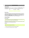
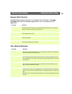
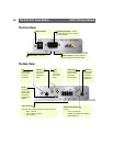
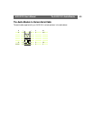
The Front Panel
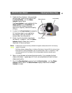
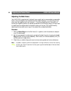
The Rear Panel
Power Connector
Power Indicator - Normally lit.
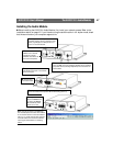
Serial Port Connector - Connect
the serial cable from here to the serial
port on the camera.
Activity Indicator - Lights up when the
camera has configured the audio module.
Level In/Level Out
The colors used to indicate the input and output levels are:
• Green - Level OK
• Yellow - Risk for overload
•Red - Overload
Terminal Block Connector
Used for:
• Line-In (e.g. CD, radio)
• Speaker-out (headphones or speakers
without amplifier)
Volume In
Level control for
input. Use a
screwdriver to
adjust.
In
3.5mm socket
for connection
of external
microphone.
Mic
Built-in
omni-direc-
tional micro-
phone.
Volume Out
Level control for
speaker volume.
Use a screw-
driver to adjust.
Line Out
3.5mm socket
for speakers
with built-in
amplifier, e.g.
PC speakers.
Int-Ext
Set to Int for
internal micro-
phone or Ext
for external
microphone or
Line-In.