


The Unit Connectors AXIS 2120 User’s Manual
64
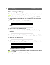
The Physical Connector
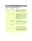
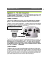
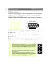
A single 9-pin D-sub connector provides the physical connection for the RS- 232 serial
interface of the AXIS 2120. This interface is for use with an external modem and is
suitable for speeds of up to 115kbps.
A diagram of the RS-232 connector complete with pinout information is shown below.
For pinout information concerning the
AXIS 2191 Audio Module, see page 53.
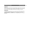
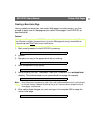
The IO Connector
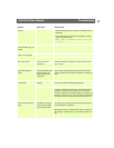
A 4-pole connector is provided for auxiliary IO connections to the AXIS 2120.
Physical Connector
The IO connector provides the interface to a single digital output and a single digital input.
A diagram for the connector, complete with a pinout table, is provided below:
Pin Function
1 CD (Carrier Detect) A view of the RS-232 connector as seen from
the rear of the AXIS 2120
2 RXD (Receive Data)
3 TXD (Transmit Data)
4 DTR (Data Terminal Ready)
5 GND (Ground)
6 DSR (Data Signal Ready)
7 RTS (Return To Send)
8 CTS (Clear To Send)
9 RI (Ring Indicator)
Pin Function
1 Common Ground
2 Positive Connection for DC Power Input or Output:
Electrically in parallel with the derived DC power for the unit, this pin may be used as a power
input or output. As a power input it can be used for remote applications to supply the AXIS
2120 via an external direct current source; for example, a 9-15V DC battery supply. Used as a
power output, it can drive the photo coupled input or other equipment; such as an infrared
sensor. The output voltage level is dependent upon the input voltage to the unit. A maximum
current of 50mA can be sourced from the DC output.
3 Digital Input (photo-coupled anode):
Voltages 5-24V DC will activate the input. It is possible to use pin 2 to source the input.
4 Digital Transistor Output:
With a maximum load of 100mA and maximum voltage of 24V DC, this output has an
open-collector NPN transistor with the emitter connected to pin 1. If it is to be used with an
external relay, a diode must be connected in parallel with the load for protection against any
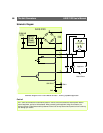
voltage transients - as detailed in the Schematic Diagram, on page 66. Important!
Connecting AC to the transistor output will damage the unit.
54
6
78
9
321
2
1
3
4