


AXIS 2120 User’s Manual The Unit Connectors
63
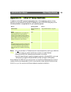
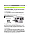
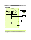
Appendix D - The Unit Connectors
This section provides a detailed overview of the two supported product connectors; namely
the Serial Connector and IO Connector. It also includes a schematic diagram describing
how the AXIS 2120 is connected for a typical application:
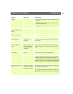
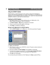
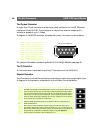
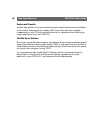
The Auto Iris Connector
The AXIS 2120 is supplied with a varifocal DC Iris lens that automatically regulates the
amount of light entering the camera, and provides a distortion free wide-angle zoom.
The power and control signalling required for automatically adjusting the lens is supplied
by the Auto Iris Connector that attaches to the lens via a connecting cable. The connector
is located at the base of the camera, as illustrated below:
The AXIS 2120 is delivered with the Auto Iris cable already attached to the connector, and
with the Auto Iris functionality enabled by default. Should you experience any problem
with overexposure or white balance adjustment in your camera, check that the cable is
firmly attached to the Auto Iris connector. Otherwise, the Auto Iris function requires no
further intervention from the user. If you are unable to immediately resolve any apparent
fault, refer to Appendix A - Troubleshooting.
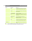
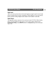
The Serial Connector
The serial connector can be used for several purposes. In the absence of a local network
connection, the serial connector provides a physical interface for connecting a modem or
computer to the AXIS 2120. When a local network connection is unavailable at the point
of installation, connect your PC to this connector using the supplied Null Modem Cable to
initially configure your product. If you intend to use the AXIS 2191 Audio Module with
your network camera, then this is the connector used for connecting it.
DC-Iris cable. Connected to the lens upon delivery,
this cable supplies the power and electronic signal-
ling to the lens from the DC Iris connector.
Below: DC Iris connector
- with the cable removed.