


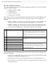


50
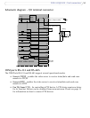
AXIS 241Q/241S - Unit connectors
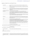
The I/O terminal connector
This section describes the pinout and interface support provided by the 12-pin I/O terminal
connector, which includes:
• 4 digital transistor outputs
• 4 digital inputs
• an RS-485 interface
• auxiliary power and GND
The terminal connector is used in applications for motion detection, event triggering, time
lapse
recording, alarm notification via email, and image storage to FTP locations, for
example.
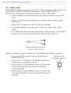
• Inputs
- Example: a push button. If the button is pressed, the state changes, and
the input will be active (shown under Event Configuration > Port Status).
• Outpu
ts - Example: an alarm device that can be activated from Output buttons
on the Live View page or as an action to an Event Type. The output will show as
active (in Event Configuration > Port Status), if the device is activated.
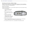
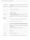
The Axis video server includes one (green) 12-pin connector
block. Connect input/output
devices to this block:
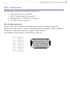
1. Loosen the corresponding screw on top of the pin
on the connector block (see the
table above to determine which pin to use).
2. Push the cable into the connector block and secure it by fastening the screw.
3. Once all devices are connected, connect the connector block to the video server’s
terminal connector.
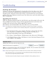
Pin Function Description
1 Auxiliary DC Power Input 7-20 VDC/min 8W. Electrically connected in parallel with the power
connector, this provides an auxiliary connection for mains power to
the unit. If the product is powered via this pin, use a fuse (rating: 1A
Slow).
This pin can also be used to power auxiliary equipment, 9vDC max
100mA.
2GND Ground
3 Digital Input 1 Connect to GND to activate or
leave floating (or unconnected) to
deactivate.
4 Digital Input 2
5 Digital Input 3
6 Digital Input 4
7 Transistor Output With a maximum load of 100mA and maximum voltage of 24V DC, this
output has an open-collector NPN transistor with the emitter
connected to pin 2 (GND). If it is to be used with an external relay, a
diode must be connected in parallel with the load for protection
against any voltage transients.
8 Transistor Output
9 Transistor Output
10 Transistor Output
11 RS-485 - A (non-inverting) A half-duplex RS-485 interface for controlling auxiliary equipment,
PTZ devices, for example.
12 RS-485 - B (inverting)