


8
AXIS 241Q/241S - Product description
Switches & connectors
DIP switch (AXIS 241Q) - A corresponding line termination switch is supplied for each
video input. All units are shipped with line termination enabled for each video input, that
is, with the DIP switch set in the down position.
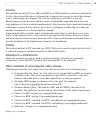
DIP switch (AXIS 241S) - Upon delivery the dip
switch on the AXIS 241S is configured
for composite video input, as follows:
Note:
If the video source is to be connected in parallel with other equipment, disable the input termination by
turning the corresponding DIP switch to the up position (OFF). Failure to do so may cause reduced image
quality.
Control Button - Press this button to restore the factory default settings, as described in
Resetting to the factory default settings, on page 4
8, or to install the video server using
AXIS Internet Dynamic DNS Service
(See the Axis Video Server Installation Guide).
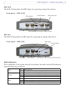
Video Input -
The video input is connected using a coax/BNC connector. Physical
connections made using 75 ohm coaxial video cable have a recommended maximum
length of 800 feet (250 meters).
Video Output (AXIS 241S only) - Loopthrough connection to the video signal
from the
Video In connector. Terminated with a coaxial/BNC connector. Allows direct connection of
an external monitor for example. Set DIP switch to ON when in use.
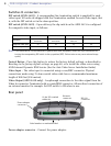
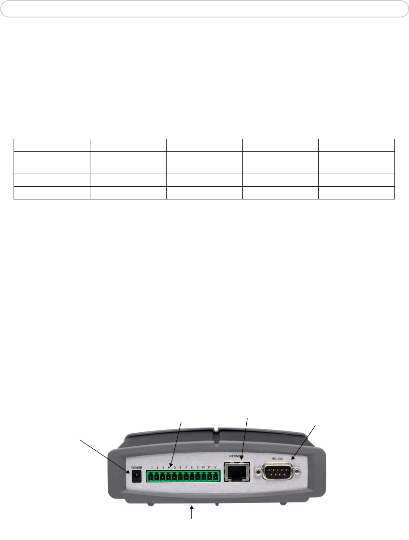
Rear panel
Power adapter connector - Connect the power adapter.
Switch 1 2 3 4
Description
75 ohm video
in
termination
75 ohm video out
termination
Connects video in and
video out
Not used
Composite video input on off on n/a
Y/C video input on on off n/a
Power adapter
connector
12-pin I/O terminal
connector
RS-232
connector
Network
connector
Serial number on underside label