


16 en | VG4 Firmware Updates via the CTFID AutoDome Modular Camera System
F.01U.097.269 | 1.06 | 2011.09 Firmware Update Manual Bosch Security Systems, Inc.
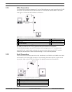
2.3.1 Bilinx Connections
To create a Bilinx interface between a PC and a VG4 AutoDome you must have a Bosch VP-USB
connector. The connector has a USB connector on one end and a female BNC on the other
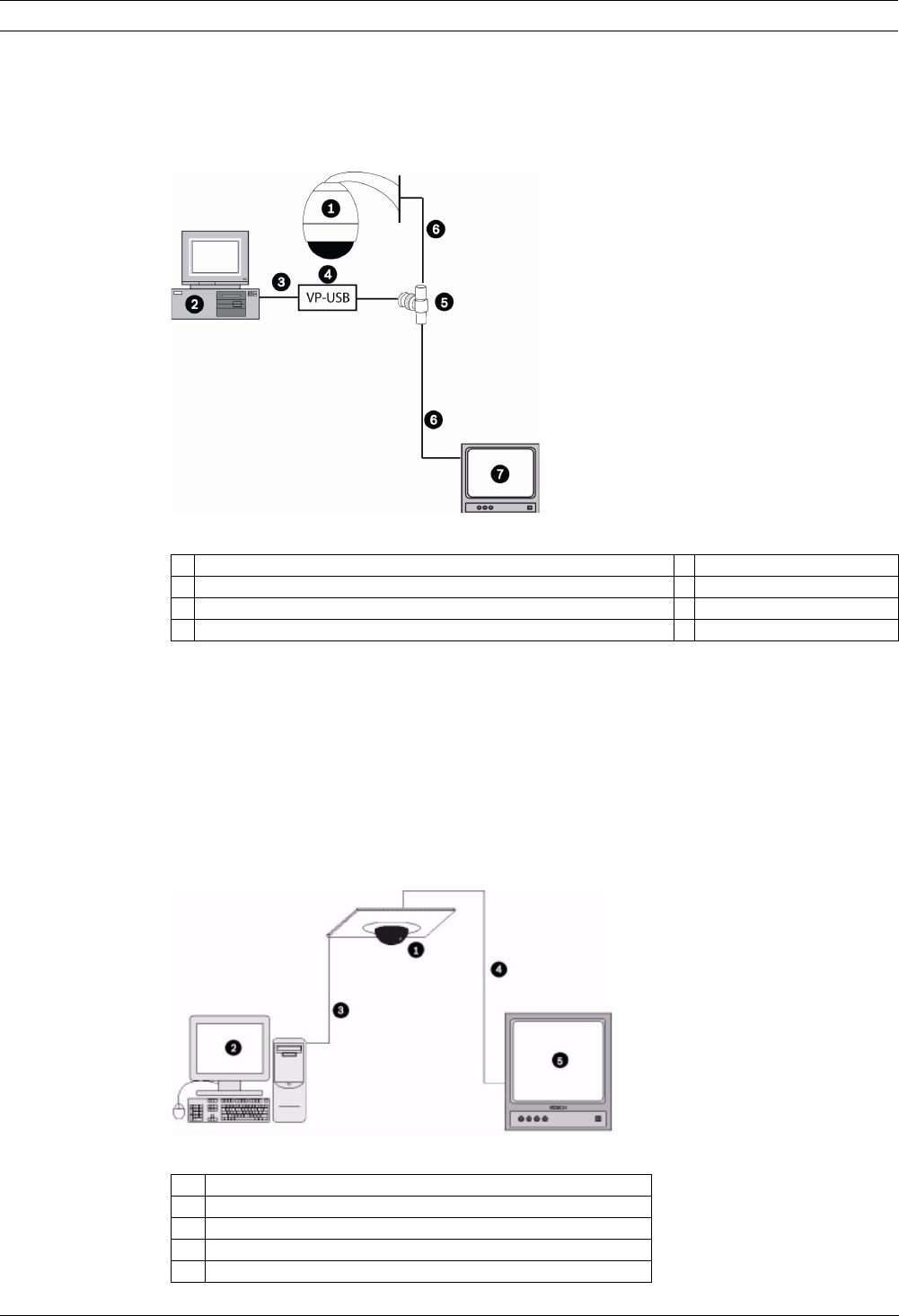
end. Figure 2.2 illustrates the interface connections:
Figure 2.2 PC to VG4 AutoDome Bilinx Connections
It is recommended that the CTFID software be installed prior to connecting the hardware to
the USB port. Refer to the CTFID Installation Manual for additional information.
To see the device output, use a CCTV monitor with looping inputs or a T connector (not
provided) for the coaxial cable, and plug the second coaxial cable into the CCTV monitor.
Ensure that the monitor is either auto-terminating or is set to low impedance.
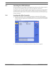
2.3.2 Serial Connections
The CTFID can also communicate with a VG4 AutoDome via an RS232 or an RS485 serial cable
connected to a PC with a DB9 connection. The following illustration depicts a typical serial
connection (refer to the CTFID User’s Manual for detailed connection instructions) .
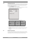
Figure 2.3 PC to VG4 AutoDome Serial Connections
1 AutoDome version 5.10 or higher, and another Bilinx device 5 BNC “T” connector
2 PC running CTFID software 6 Coax to input of monitor
3 USB Port 7 Typical CCTV monitor
4 VP-USB adapter
1 AutoDome 100, 200 or 300 Series AutoDome
2 PC Running CTFID Software
3 RS-232 Connection
4 Coax to Monitor Input
5 Typical CCTV Monitor