


12 en | Using the AutoDome 700 Series AutoDome 700 Series IP PTZ Camera
F.01U.215.777 | 1.0 | 2011.07 User Manual Bosch Security Systems, Inc.
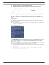
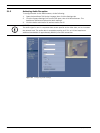
1. To control a peripheral, click the appropriate controls.
2. Move the mouse cursor over the video image. Additional options for controlling
peripherals are displayed with the mouse cursor.
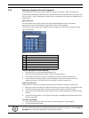
3. To manually pan throughout the image area, move your cursor over any part of the live
video. The image area displays a directional arrow ( ), then click and hold the
right mouse key to pan the camera.
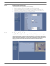
Digital I/O
The alarm icon is for information purposes and indicates the status of an alarm input: When
an alarm is triggered, the icon lights up blue. The device’s configuration determines whether
the alarm is displayed, as well as additional details (see the AutoDome 700 Series online
help).
Triggering Relay
You can switch connected units using the relays in the AutoDome 700 Series (for example
lights or door openers).
To activate this, click the icon for the relay next to the video image. The icon will be red
when the relay is activated.
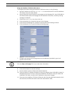
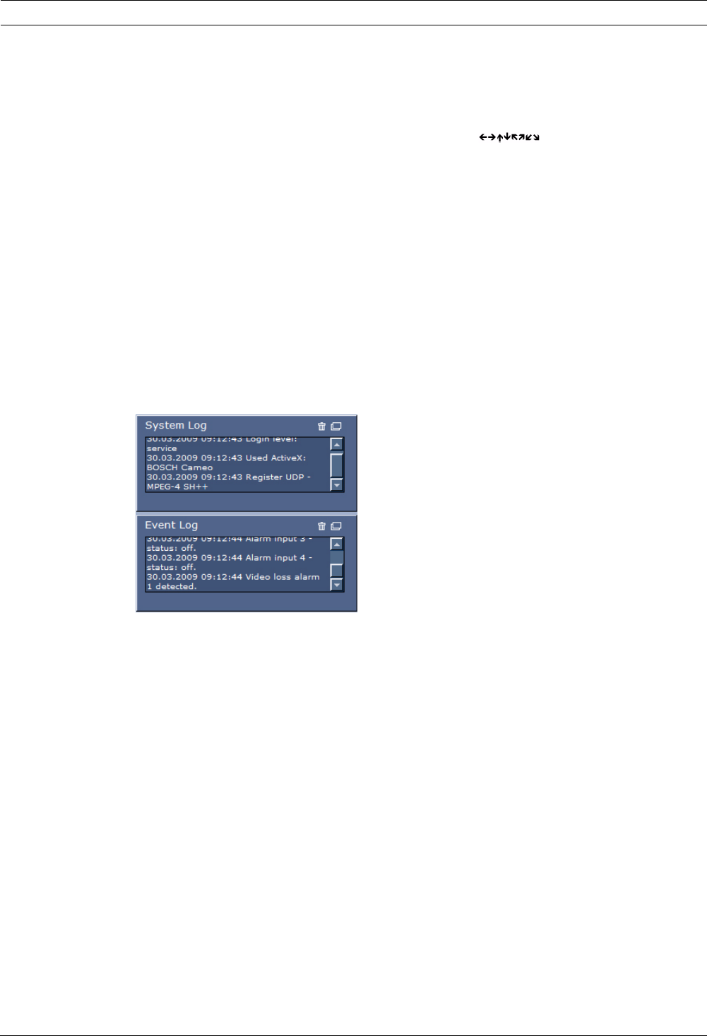
System Log / Event Log
The System Log field contains information about the operating status of the AutoDome 700
Series and the connection. You can save these messages automatically in a file (see the
AutoDome online help).
Events such as the triggering or end of alarms are shown in the Event Log field. You can save
these messages automatically in a file (see the AutoDome online help).
1. If you want to delete the entries, click the delete icon in the top right-hand corner of the
relevant field.
2. If you want to view a detailed log, click the icon in the top right-hand corner of the
relevant field. A new window will open.