


1-4
Cisco Video Surveillance System 2621 IP Dome User Guide
OL-24129-02
Chapter 1 Overview
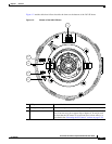
IP Camera Overview
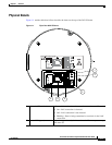
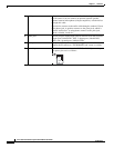
3 Audio port Allows the connection of the audio Y cable that is provided with
the IP camera. You can connect an optional external speaker,
optional external microphone (with pre-amplifier), or both devices
through this cable.
Each device connects to the audio cable through a standard 3.5 mm
mini phone jack. A speaker connects to the green jack, which is
labeled “Audio Out.” A microphone connects to the pink jack,
which is labeled “Audio In.”
4 GPIO ports General purpose input/output (GPIO) terminal block that includes
2 input ports (labeled DI1, DI2), 2 output ports (labeled DO1,
DO2), and 4 ground ports (labeled GND).
5 LAN port Accepts a twisted pair category 5 or higher network cable to
connect the IP camera to a 10/100BASET hub, router, or switch.
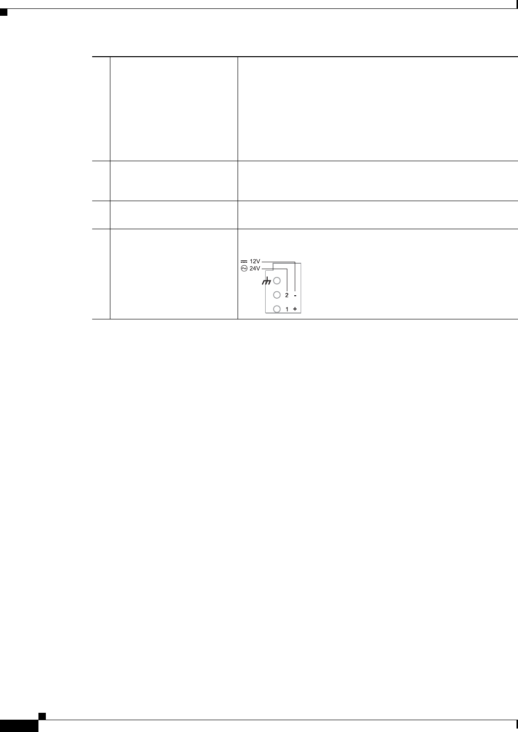
6 Power input Provides for the connection of a 12 VDC or 24 VAC power adapter.
The power pin-out is as follows: