


2-6
Cisco Video Surveillance System 2621 IP Dome User Guide
OL-24129-02
Chapter 2 Getting Started
Installing the Cisco Video Surveillance 2621 IP Dome
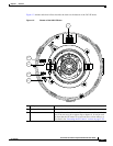
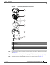
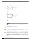
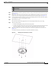
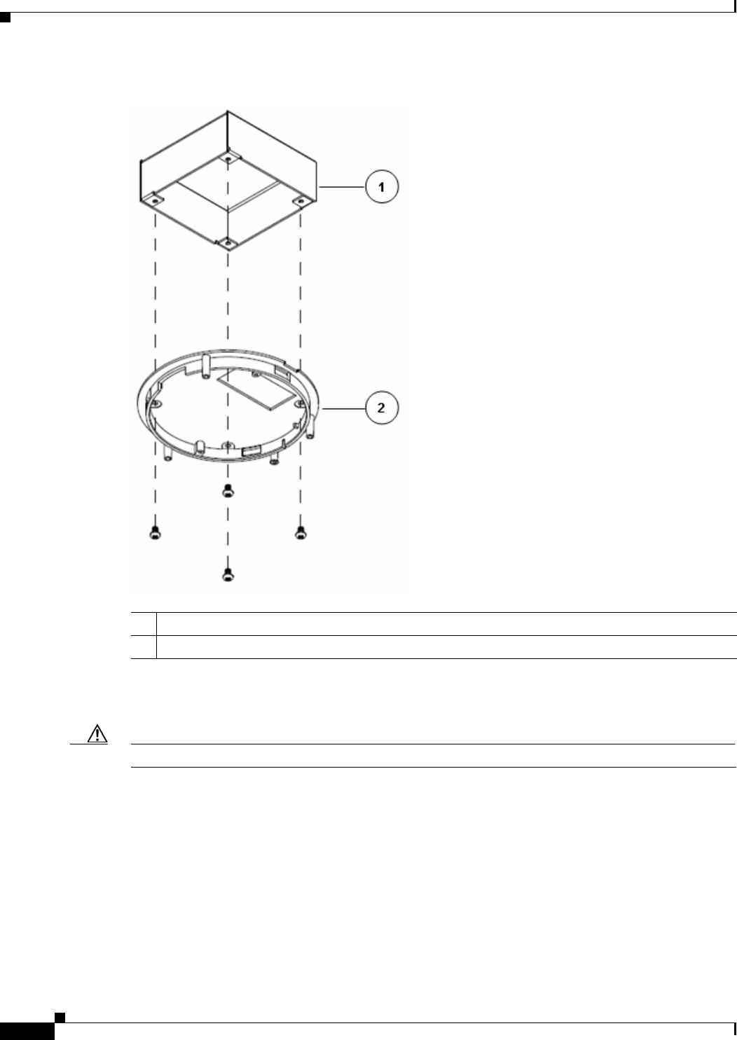
Figure 2-3 Attaching the Base Plate to a Junction Box
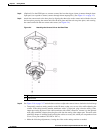
Step 5 Put the an category 5 or higher Ethernet cable through the camera housing and connect it to the LAN
port on the IP dome (see
Figure 1-1 on page 1-3).
Caution Do not lift the IP dome by the Ethernet cable.
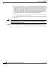
Step 6 If the IP dome will not receive PoE, put the power cable through the camera housing and connect it to
the power input on the IP dome (see
Figure 1-1 on page 1-3).
To connect a power cable, use a flat-head screwdriver to depress the brown tabs on the power input and
connect bare positive, negative, and ground wires as shown on the label that is affixed to the IP dome.
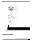
Step 7 (Optional) Connect an external speaker, microphone, or both to the Y cable, then connect the Y cable to
the audio port on the IP dome.(see
Figure 1-1 on page 1-3). The Y cable that is included in the optional
audio/video cables accessory kit can be purchased from Cisco (Cisco part number CIVS-IPCA-1017=).
Each device connects to the audio cable through a standard 3.5 mm mini phone jack. A speaker connects
to the green jack, which is labeled “Audio Out.” A microphone connects to the pink jack, which is labeled
“Audio In.”
1 Junction box
2 Base plate