


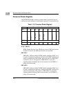
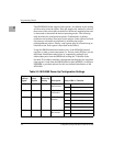

MV64360 Reset Configuration
http://www.motorola.com/computer/literature 2-3
2
MV64360 Reset Configuration
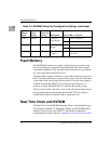
The MV64360 supports two methods of device initialization following
reset:
❏ Pins sampled on the deassertion of reset
❏ Partial pin sample on deassertion of reset plus Serial ROM
initialization via the I2C bus for user defined initialization
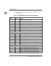
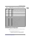
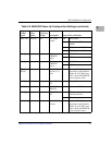
20 I PCI Bus 0 Interrupt PCI-VME INT 0 (Tempe LINT0#, PMCspan
INT 2#)
21 I PCI Bus 0 Interrupt PCI-VME INT 1 (Tempe LINT1#, PMCspan
INT 3#)
22 I PCI Bus 0 Interrupt PCI-VME INT 2 (Tempe LINT2#, PMCspan
INT 0#)
23 I PCI Bus 0 Interrupt PCI-VME INT 3 (Tempe LINT3#, PMCspan
INT 1#)
MPP[19:16] PCI_1 Interrupts,
MPP[23:20] PCI_0 Interrupts
24 O MV64360 SROM initialization active (InitAct)
25 O Watchdog Timer Expired output (WDE#)
26 O Watchdog Timer NMI output (WDNMI#)
27 I Reserved for future device interrupt
28 O Tempe ASIC (VMEbus) grant
29 I Tempe ASIC (VMEbus) request
30 O PCI6520 (PMCspan bridge) grant
31 I PCI6520 (PMCspan bridge) request
MPP[31:28] PCI_0 Arbitration Request-Grant Pairs
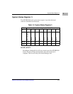
Table 2-1. MV64360 MPP Pin Function Assignments (continued)
MPP Pin
Number
Input/
Output Function