


PCI Configuration Space
http://www.motorola.com/computer/literature 2-13
2
Specification Revision 1.0b) at the rising edge of RST#. Onboard logic
will sense the states of PCIXCAP and M66EN for all devices on the bus
and select the appropriate mode and clock frequency. Software can access
the MV64360 Configuration Registers to determine the PCI mode and
clock frequency of PCI Bus 1 and PCI Bus 0. Refer to the MV64360 Data
Sheet, listed in Appendix A, Related Documentation, for details.
Voltage Input/Output (VIO) is selected on PCI Bus 1 by the position of the
PMC keying pins. Both sites should be set for the same VIO; that is, keyed
identically. If 5V VIO is selected, PCI Bus 1 reverts to PCI mode at 33
MHz.
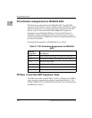
PCI Configuration Space
The MV64360 controls all PCI configuration space access from either the
CPU or PCI busses. The IDSEL assignments for MVME6100 are shown
on the following table:
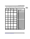
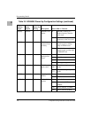
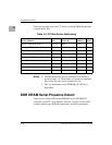
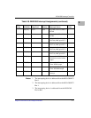
Table 2-6. IDSEL Mapping for PCI Devices
PCI Bus #
Device
Number Field
PCI Address
Line IDSEL Connection
PCI Bus 0, PCI
Bus 1
0b1_0000 AD16 MV64360 ASIC
PCI Bus 0,0 0b1_0100 AD22 PCI6520
PCI Bus 0 0b1_0101 AD21 Tempe VME Bridge ASIC
PCI Bus 1 0b1_0100 AD20 PMC Slot 0 (SCSI controller also uses
IDSEL AD20)
PCI Bus 1 0b1_0101 AD21 PMC Slot 0, Secondary PCI Agent,
IPMC slot
PCI Bus 1 0b1_0110 AD22 PMC Slot 1
PCI Bus 1 0b1_0111 AD23 PMC Slot 1, Secondary PCI Agent