


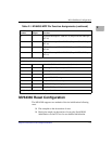
MV64360 Reset Configuration
http://www.motorola.com/computer/literature 2-7
2
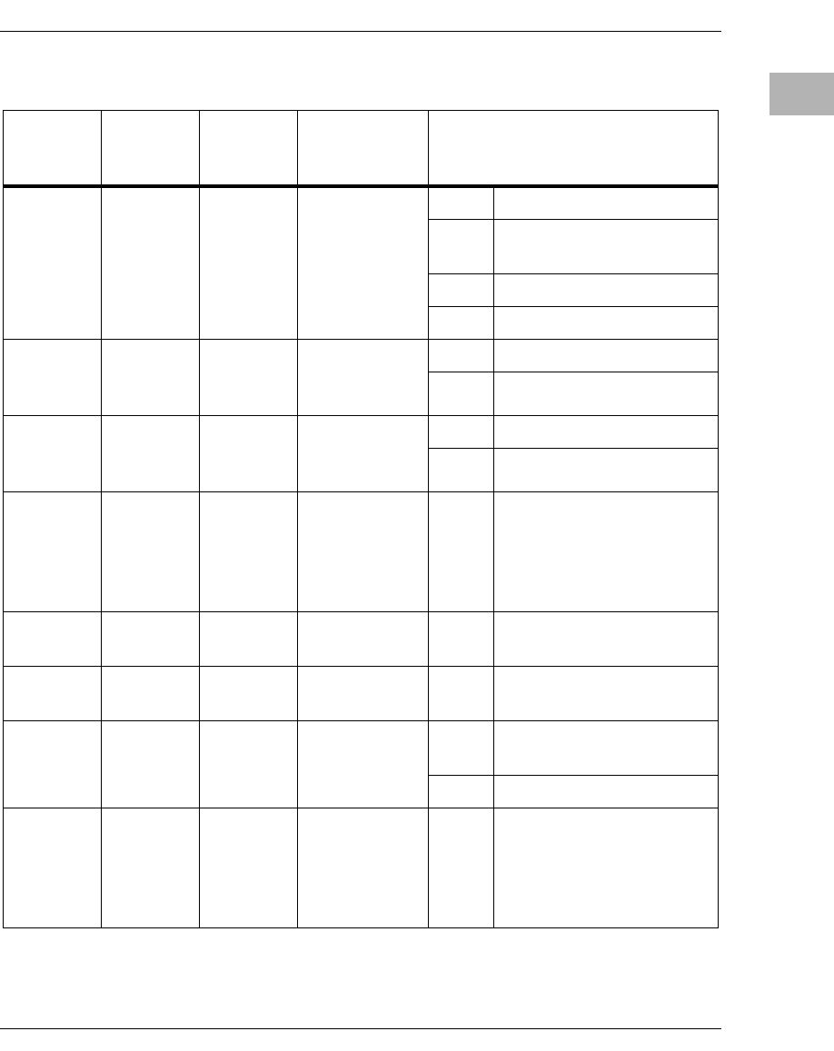
AD[31:29] Resistors 101 PCI_0 DLL
control
000 DLL disable
001 Conventional PCI mode at
66MHz
101 PCI-X mode at 133 MHz
110 PCI-X mode at 66 MHz
TxD0[0] Resistor 0 Gigabit port 0
GMII/PCS
Select
0MII/GMII
1PCS
TxD1[0] Resistor 0 Gigabit port 1
GMII/PCS
Select
0MII/GMII
1PCS
WE[3:0],
DP[3:0]
Resistor X DRAM PLL N
Divider [7:4],
[3:0]
TBD Refer to MV64360
Specification MV-S100614-
00 Rev. B (1/13/2003) page
144 for detail. MVME6100
is not using this mode.
BADR[0] Resistor 1 DRAM PLL
NP
1 Pull up NP
BADR[1] Resistor 1 DRAM PLL
HIKVCO
1 Pull down HIKVCO
BADR[2] Resistor 1 DRAM PLL
NP
0 PLL power down
(normal operation)
1 PLL power up
TxD0[6:1] Resistor X DRAM PLL M
Divider
TBD Refer to MV64360
Specification MV-S100614-
00 Rev. B (1/13/2003) page
144 for detail. MVME6100
is not using this mode.
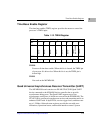
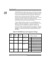
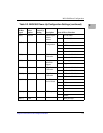
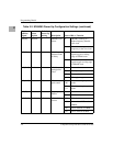
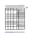
Table 2-2. MV64360 Power-Up Configuration Settings (continued)
Device
AD Bus
Signal
Select
Option
Default
Power-Up
Setting Description State of Bit vs. Function