


2-10 Computer Group Literature Center Web Site
Programming Details
2
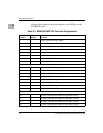
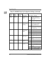
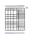
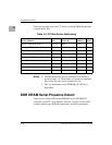
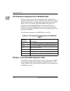
The following table shows the I
2
C devices on the MVME6100 and their
assigned device IDs.
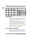
Notes 1. The SPD defines the physical attributes of each bank or
group of banks, i.e. if both banks of a group are populated,
they will be the same speed and memory size.
2. This is a dual address serial EEPROM (AT24C64A or
equivalent).
DDR DRAM Serial Presence Detect
There are two onboard SPD serial EEPROMs on the MVME6100
accessible via the I
2
C serial interface. The first 128 bytes of each SPD
contains module type, SDRAM organization, and timing parameters.
Table 2-4. I2C Bus Device Addressing
Device Function Size
Device Address
(A2A1A0)
I2C BUS
Address Notes
Memory SPD (Bank 0 and 1) 256 x 8 000b $A0 1
Memory SPD (Bank 2 and 3) 256 x 8 001b $A2 1
Reserved (PMCSpan SROM) NA 010b $A4
MV64360 User Defined Initialization 8K x 8 011b $A6 2
Configuration VPD 8K x 8 100b $A8 2
User VPD 8K x 8 101b $AA 2
Not Used NA 110b $AC
Not Used NA 111b $AE
DS1621 Temperature Sensor NA 011b $90