


2-4 Computer Group Literature Center Web Site
Programming Details
2
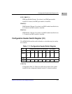
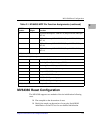
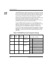
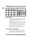
The MVME6100 board supports both options. An onboard switch setting
will be used to select the option. If the pin sample only method is selected,
then states of the various pins on the device AD bus are sampled when reset
is deasserted to determine the desired operating modes. The following
table describes the configuration options. Combinations of pullups,
pulldowns and switches are used to set the options. Some options are fixed
and some are selectable at build time by installing the proper
pullup/pulldown resistor. Finally, some options may be selected using an
onboard switch. Each option is described in the Table 6.
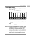
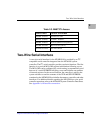
Using the SROM initialization method, any of the MV64360 internal
registers or other system components (i.e. devices on the PCI bus) can be
initialized. Initialization takes place by sequentially reading 8 byte
address/data pairs from the SROM and writing the 32-bit data to the
decoded 32-bit address until the a data pattern matching the last serial data
item register is read from the SROM (default value 0xffffffff). An 8 Kbyte
EEPROM is provided onboard for this user defined initialization of the
MV64360.
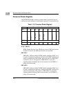
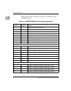
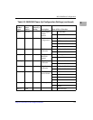
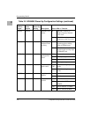
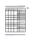
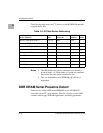
Table 2-2. MV64360 Power-Up Configuration Settings
Device
AD Bus
Signal
Select
Option
Default
Power-Up
Setting Description State of Bit vs. Function
AD[0] switch X SROM
Initialization
0 No SROM initialization
1 SROM initialization enabled
AD[1] Resistor 1 DRAM Pads
Calibration
0 Calibration Disabled
1 Calibration Enabled
AD[3:2] Resistors 11 SROM Device
Address
00 1010000 ($A0)
01 1010001 ($A2)
10 1010010 ($A4)
11 1010011 ($A6)
AD[4] Fixed 1 Internal 60x
Bus Arbiter
0 Internal arbiter disabled
1 Internal arbiter enabled