


12 of 59
2.5 ALARM IN- / OUT INSTALLATION
Alarm- in- and outputs are connected to the screwless terminal at backside of the camera.
For Details to input/output circuit refer to Attachment A.
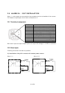
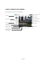
2.5.1 Terminal pin assignment:
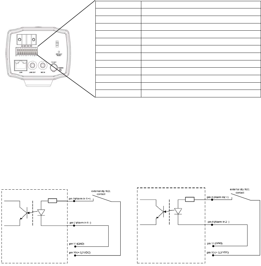
Contact Description
1 Alarm IN 1 + (max 50 V DC)
2 Alarm IN 1 -
3 Alarm IN 2 + (max 50 V DC)
4 Alarm IN 2 -
5 Relay COM (max. 24 V DC / 1 A)
6 Relay N.C. (max. 24 V DC / 1 A)
7 Relay N.O. (max. 24 V DC / 1 A)
8 RS-485+
9 RS-485-
10 + 3,3 VDC Output
11 GND
Both alarm inputs are opto-coupler inputs and require DC Voltage 3~50 VDC for activation.
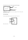
2.5.2 Alarm Inputs
Following connection methods are possible:
A) Installation of dry N.O. contact with camera power source
Alarm In 1 Alarm In 2