


8 of 59
2 HARDWARE INSTALLATION
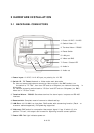
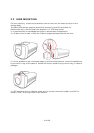
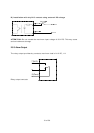
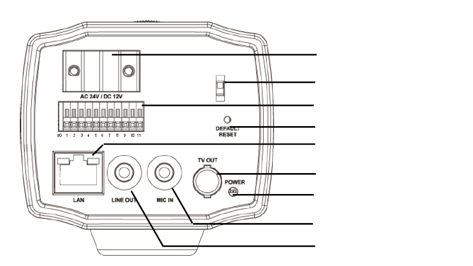
2.1 BACKPANEL CONNECTORS
1. Power input: 12 V DC / 24 V AC input, no polarity for 12 V DC
2. Switch IP / TV Teset: Network or Video mode work alternative
For lens and camera adjustment connect a video monitor to the BNC socket, turn
the switch to "TV Test", then turn OFF and turn ON power (no network streaming in
this mode)
For network streaming switch back to "IP Cam" and OFF and turn ON power (no BNC
video out in "IP Cam" mode.
3. Terminal Alarm / RS485: Screwless terminal for alarm inputs / outputs and RS-485
interface.
4. Reset switch: Complete reset of camera to default settings
5. LAN-Port: 10/100 Mbit Lan Interface, RJ45 socket with autosensing function (Patch - or
crossover cables supported), PoE powering supported
6. Video out: BNC socket for composite video output signal 1 V pp. If switch (2) is in
position "TV test", this output can be used for adjusting lens and camera position.
7. Power LED: Red light indicates power on.
1. Power 12 VDC / 24 VAC
2. Switch Video / IP
3. Terminal Alarm / RS485
4. Reset Switch
5. LAN port
6. Video out BNC
7. Power / Status LED
8. Audio in
9. Audio out