


Genie Monochrome Series-GigE Vision Camera Operational Reference • 49
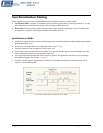
General Inputs
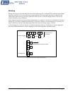
External Input Signal Opto-coupler & Debounce Circuit
• Genie provides two sets of opto-coupled inputs for either RS422 or TTL signals. These can be used as external
trigger sources.
• See "
12-Pin Hirose Connector Signal Details" on page 90 for connector pinout and electrical information. The
cable shell and shield should electrically connect the Genie chassis to computer chassis for maximum EMI
protection.
• For external triggers, a rising edge signal is suggested to minimize the time it takes for the opto-coupler to
change state. (The opto-coupler response time is typically 10µs for rising edge compared to 50μs for falling
edge).
• Each input incorporates a signal debounce circuit (following the opto-couple) to eliminate short noise
transitions that could be wrongly interpreted as a valid pulse. The duration is user-programmable from 1µs to
255µs with CamExpert.
• Note, the external trigger input propagation delay is dependent on the signal used to activate the opto-coupled
input. Typical delays are 3 µs for Active Open and 5 µs for Active Close.
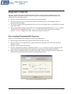
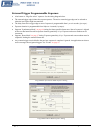
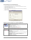
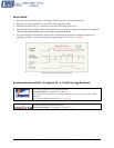
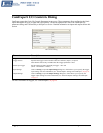
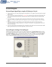
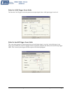
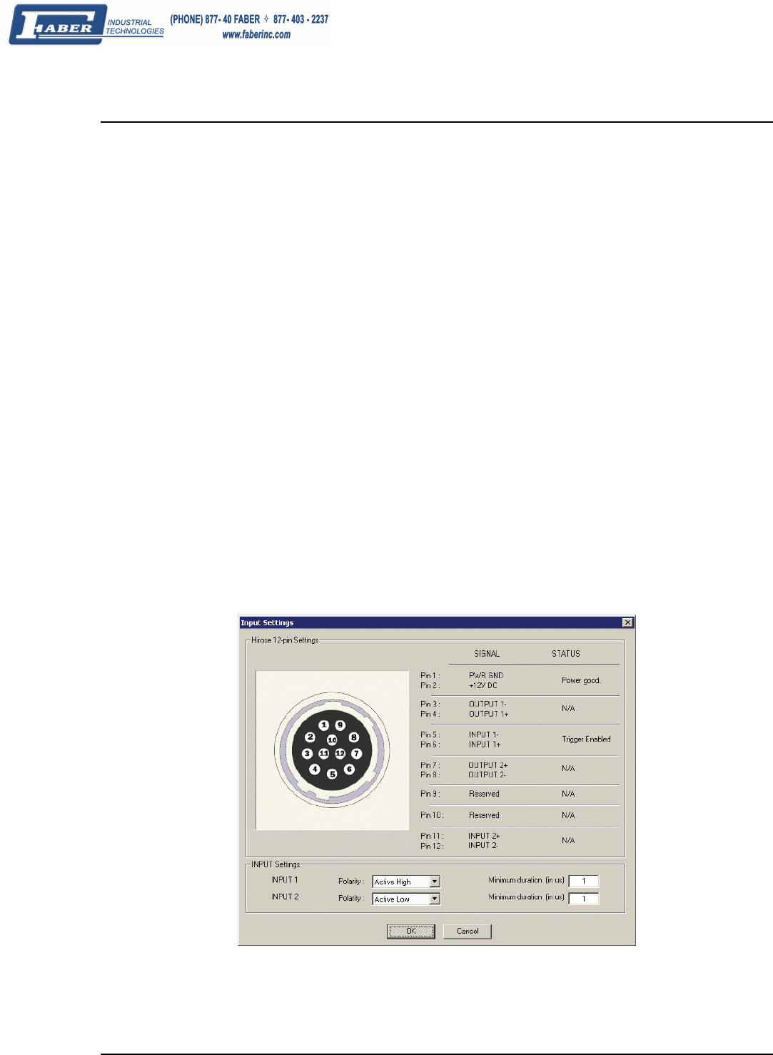
General Inputs: Settings Via CamExpert
CamExpert provides control of inputs via the I/O Controls Parameters tab. The Input Settings dialog box allows
you to view the signal and status for each pin on the Hirose connector. The Polarity drop-down list boxes, located
in the INPUT Settings area, allow you to specify the polarity of the Input 1 and Input 2 as either Active High or
Active Low. The Minimum duration field for each input, allows you to specify the minimum trigger length (1-
255µs ) so that input transitions are debounced to prevent unwanted trigger events.
Input Settings Dialog