Laufwerk / Drive Mechanism
5 - 10 GRUNDIG Service-Technik
3.3 Brake Band Adjustment
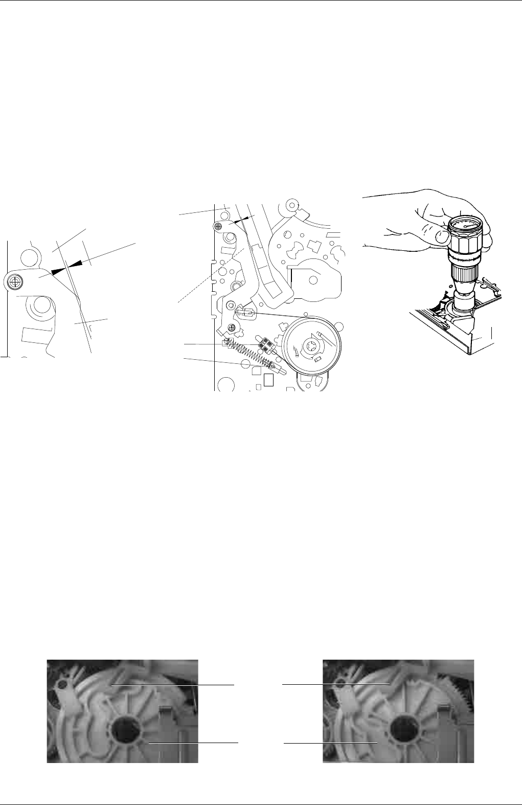
– Lower the cassette compartment (chapter 1.2). Turn the pulley of the
threading motor (Fig. 4) in the "threading" direction until the cam
wheel takes the position shown in Fig. 22.
– Adjust the brake band by means of the tape tension adjusting tool
(from the underside of the tape deck) so that the edge of the elbow
of the tape tension arm overlaps with the left inner edge of the left
guide (see Fig. 20).
3.4 Tape Tension Adjustment
– Play a cassette (E 180) starting from the beginning of the tape.
– Measure the tape tension between the full-track erase head (Fig. 17,
Pos. 16) and the reverse roller (Fig. 17, Pos. 23) by means of the
tentelometer (for this press the full-track erase head to the left).
– Adjust the spring (pos.11) to a tape tension of 0.24N ±0.02N (24g
±2g) by means of the tape tension adjustment tool (Fig. 20).
3.5 Checking the Friction Clutch
– Lower the cassette compartment (chapter 1.2). Turn the pulley of the
threading motor (Fig. 4) in the "threading" direction until the cam
wheel takes the position shown in Fig. 22.
– Place the torque meter on the right reel (Fig. 21).
– Turn the capstan motor to move the right reel clockwise.
– Keep turning until the reading on the torque meter does not change
any more (Fig. 21).
– The torquemeter must read 10.5 mNm ±25% (105gf-cm ±25%).
3.6 Checking the Reverse Brake
– Lower the cassette compartment (chapter 1.2). Turn the pulley of the
threading motor (Fig. 4) in the "threading" direction until the cam
wheel takes the position shown in Fig. 23. In doing so, the swivelling
gear (Pos. 17J) must engage with the left gearwheel (Pos. 18J).
– Place the torque meter on the right reel and turn the latter counter-
clockwise until the reel just starts to slip (Fig. 21).
– The torquemeter must read 7mNm ±3mNm (70gf-cm ±30gf-cm).
Bandzugfühlhebel
Tension arm
linke innere Führungskante
Guiding left
Bandzugjustierung
Tape tension adjustment
Bremsbandjustierung
Brake band adjustment
Ø ÷ 0.5mm
Fig. 20 Fig. 21
Pos. 41G
Pos. 45A
Fig. 23Fig. 22
3.3 Bremsbandeinstellung
– Cassettenschacht absenken (Kap. 1.2). Riemenscheibe des Fädel-
motors (Fig. 4) in Drehrichtung "Einfädeln" drehen, bis das Kurven-
rad in der abgebildeten Stellung (Fig. 22) ist.
– Mittels Bandzug-Einstellwerkzeug (von der Unterseite des Lauf-
werks) das Bremsband so einstellen, daß die Nase des Bandzug-
fühlers deckungsgleich mit der linken inneren Führungskante der
Führung links ist (Fig. 20).
3.4 Bandzugeinstellung
– Eine Cassette (E180) vom Bandanfang ausgehend wiedergeben.
– Mit dem Tentelometer den Bandzug zwischen Hauptlöschkopf
(Fig. 17, Pos. 16) und der Umlenkrolle (Fig. 17, Pos. 23) messen
(dazu den Hauptlöschkopf nach links drücken).
– Mit dem Bandzug-Einstellwerkzeug die Feder (Pos.11) auf einen
Bandzug von 0,24N ±0,02N (24g ±2g) einstellen (Fig. 20).
3.5 Kontrolle der Rutschkupplung
– Cassettenschacht absenken (Kap. 1.2). Riemenscheibe des Fädel-
motors (Fig. 4) in Drehrichtung "Einfädeln" drehen, bis das Kurven-
rad in der abgebildeten Stellung (Fig. 22) ist.
– Drehmomentmesser auf den rechten Wickelteller aufsetzen
(Fig. 21).
– Capstanmotor so drehen, daß sich der rechte Wickelteller im
Uhrzeigersinn bewegt.
– So lange drehen, bis sich die Anzeige am Drehmomentmesser nicht
mehr verändert (Fig. 21).
– Drehmoment muß 10,5mNm ±25% (105gf-cm ±25%) sein.
3.6 Kontrolle der Reversebremse
– Cassettenschacht absenken (Kap. 1.2). Riemenscheibe des Fädel-
motors (Fig. 4) in Drehrichtung "Einfädeln" drehen, bis das Kurven-
rad in der abgebildeten Stellung (Fig. 23) ist. Dabei muß das
Umlenkrad (Pos. 17J) in das linke Zahnrad (Pos. 18J) eingreifen.
– Drehmomentmesser auf den rechten Wickelteller aufsetzen und
entgegen dem Uhrzeigersinn so lange drehen, bis der Wickelteller
leicht durchrutscht (Fig. 21).
– Wert am Drehmomentmesser muß 7mNm ±3mNm (70gf-cm
±30gf-cm) betragen.


