


GV44…, GV45…, GV46… Abgleichvorschriften / Adjustment Procedures
GRUNDIG Service-Technik 3 - 7
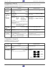
2.4 Family Board – Video (VS)
Test Equipment: Oscilloscope, 10:1 Test Probe, Frequency Counter, Stabilized Power Supply, Colour Generator, Test Cassette.
Service work after replacing the Family Board: Adjustment no. 3, 5
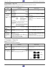
Adjustment Preparation Adjustment Procedure
1. EE-Level / Sync-
Level Control,
R3635 (EE)
2.1 Frequency
Deviation Sync
Value, R3752
(SV)
2.2 White Value,
R3755 (WV)
3. Video Record
Voltage, R3707
(YWV)
4. Playback Amplitu-
de, R3768 (PBA)
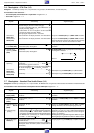
5. FM-Reference
Level Adjustment
for Automatic
Contour Control
Set amplitude with R3635 (EE) to 0.5V
PP
.
Set frequency counter with R3752 (SV) to 3.8MHz.
Solder in C2605.
Increase the voltage of the power supply slowly, till both
beams coincide.
Set frequency counter to 4.85MHz with R3755 (WV).
Solder in C2605.
Set FM signal with R3707 (YWV) to 0.22V
PP
.
Set amplitude with R3768 (PBA) to 2V
PP
.
Press the button 1. The display shows on the left "
PICT
"
and on the right "
A1
". On successful adjustment the video
recorder switches to Pause
To cancel the service function: Press the "Standby" button
or disconnect the recorder from the mains.
Feed in a white test pattern (100% white, 1V
PP
, 0.3V sync
component, 0.7V CVS component).
Oscilloscope: ...................................................... MP
31
AV recording.
Unsolder C2605.
Frequency counter:............................................. MP
32
AV recording.
Frequency counter:............................................. MP
32
Oscilloscope: Channel A: IC7510-(42),
Channel B: Marking beam
Trigger: IC7510-(33), switch
oscilloscope to DC.
AV recording.
Mark the white value of the CVS signal with the unused
beam B of the oscilloscope.
Unsolder C2605.
Power Supply: Connect positive (0V) to IC7510-(42) via
a diode; cathode of the diode to pin 42.
Connect negative to chassis.
Oscilloscope: ............................. Head Amplifier, MP
1
AV recording.
Oscilloscope: ...................................................... MP
33
Play back a white test pattern (self-made recording).
Playback
Call up the service function:
– Press the Z button on the remote control handset
("
CODE – – – –
" is indicated in the display).
– Enter the code number 4 9 3 4 and press the O
button ("
SERV
" is indicated in the display).
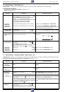
2.5 Family Board – Chroma (VS)
Test Equipment: Oscilloscope with 10:1 Test Probe.
Service work after replacing the Family Board: –
Adjustment Preparation Adjustment Procedure
1. Chroma Record
Voltage, R3693
(CWV)
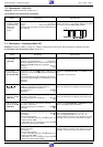
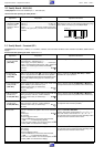
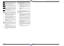
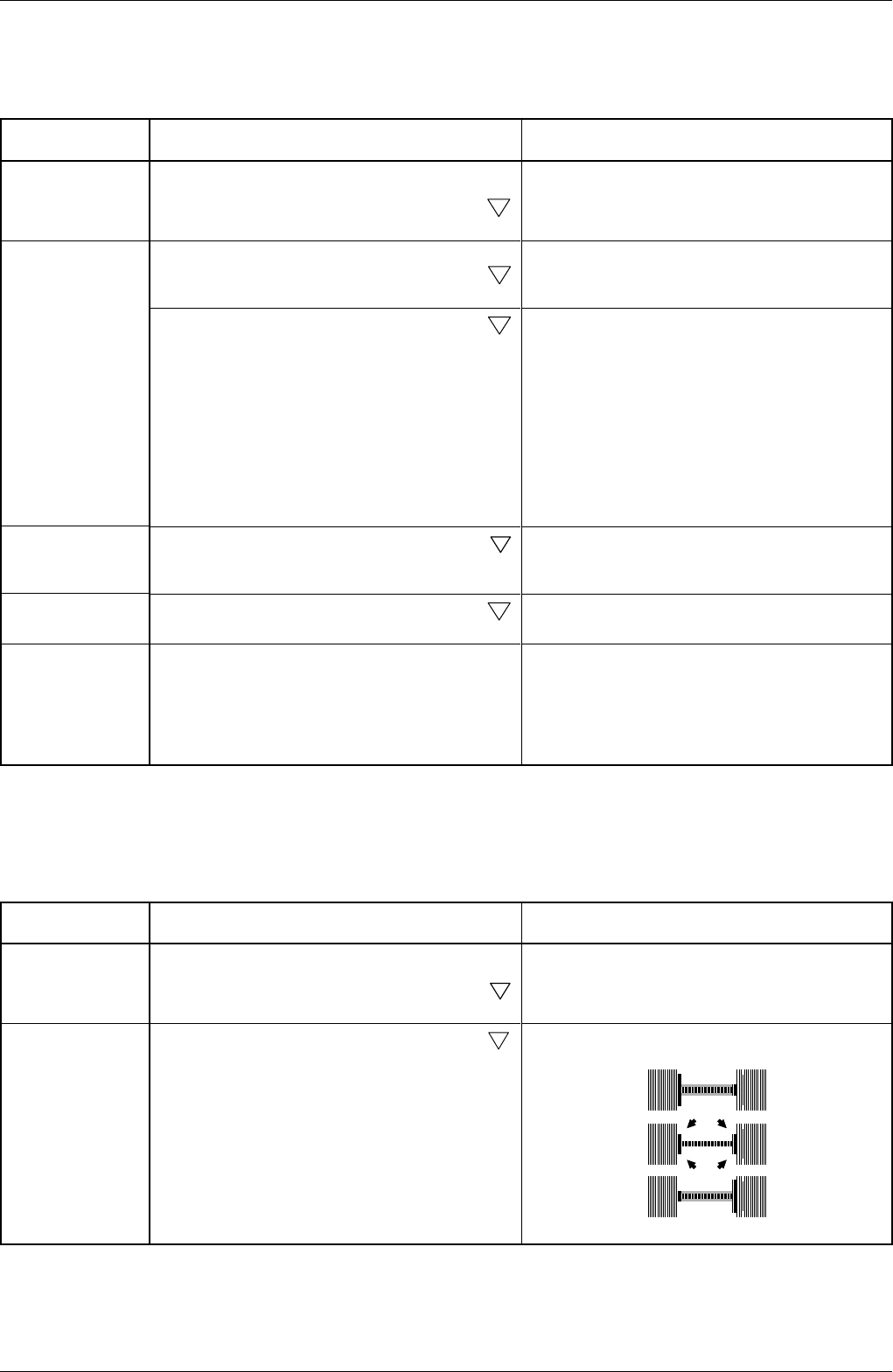
2. 627kHz Comb
Filter, R3918 (CF)
Set amplitude with R3693 (CWV) to 55mV
PP
.
Remove the short circuit.
With R3918 (CF) set the signal as shown in the oscillo–
grams below.
Incorrect
CORRECT
Incorrect
200µs/cm
Short-circuit C2552.
Feed in a colour bar test pattern.
Oscilloscope: ............................. Head Amplifier, MP
1
Record.
Oscilloscope: ...................................................... MP
41
Trigger: ................................................. HI pulse 1506-3.
Play back a self-made recording (red test signal).