


11
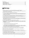
Electrical Connections
All electrical connections must
be made by a qualified electrician! Failure to
comply may cause serious injury!
General Electrical Cautions
This machine must be grounded in accordance with
the National Electrical Code and local codes and
ordinances. This work should be done by a qualified
electrician. The machine must be grounded to protect
the user from electrical shock.
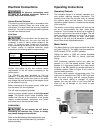
Wire Sizes
For circuits which are far away from
the electrical service box, the wire size must be
increased in order to deliver ample voltage to the
motor. To minimize power losses and to prevent
motor overheating and burnout, the use of wire sizes
for branch circuits or electrical extension cords
according to the following table is recommended:
Conductor
Length
AWG Number
230/460 Volt Lines 120 Volt Lines
0 – 50 Ft. No. 14 No. 14
50 – 100 Ft. No. 14 No. 12
Over 100 Ft. No. 12 No. 8
Figure 4
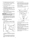
Confirm that power at the site matches power
requirements of the mill before connecting to the
power source.
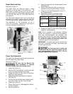
The JTM-4VS has been pre-wired for 230 volt
operation. To change from 230V to the other voltage
offered, remove the junction box cover on the motor
and change the wires according to the diagram found
on the inside of the cover.
Before connecting to the power source, make sure
that the switch is in the off position.
The mill must be properly grounded.
Check for proper spindle rotation in the high-speed
range. The spindle should rotate clockwise when
viewed from the top of the machine. If the spindle
rotates counter-clockwise, disconnect from power
and switch two of the three power leads.
Lubrication
Do not operate the mill before
lubricating the machine fully. Failure to comply
may cause damage to the machine.
Refer to the Maintenance/Lubrication section and
make sure the machine has been fully lubricated
before operating.
Operating Instructions
Operating Controls
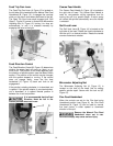
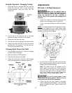
The lubrication system is a manually operated, one-
shot system requiring operator intervention. The
operator must lower the one-shot lever to lubricate
the machine ways and ball screws. The one-shot
lubrication system reservoir is located on the left side
of the machine.
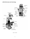
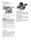
The position of the milling machine mill head can be
set up to accommodate the work piece being
machined. The mill head can be set up for angles to
the left or right and for fore and aft angles. The mill
head can also be rotated on its turret. The ram can
be moved back and forth to reach work piece
locations at the fore and aft extremes of worktable
travel. Refer to the Adjustments section.
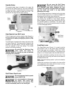
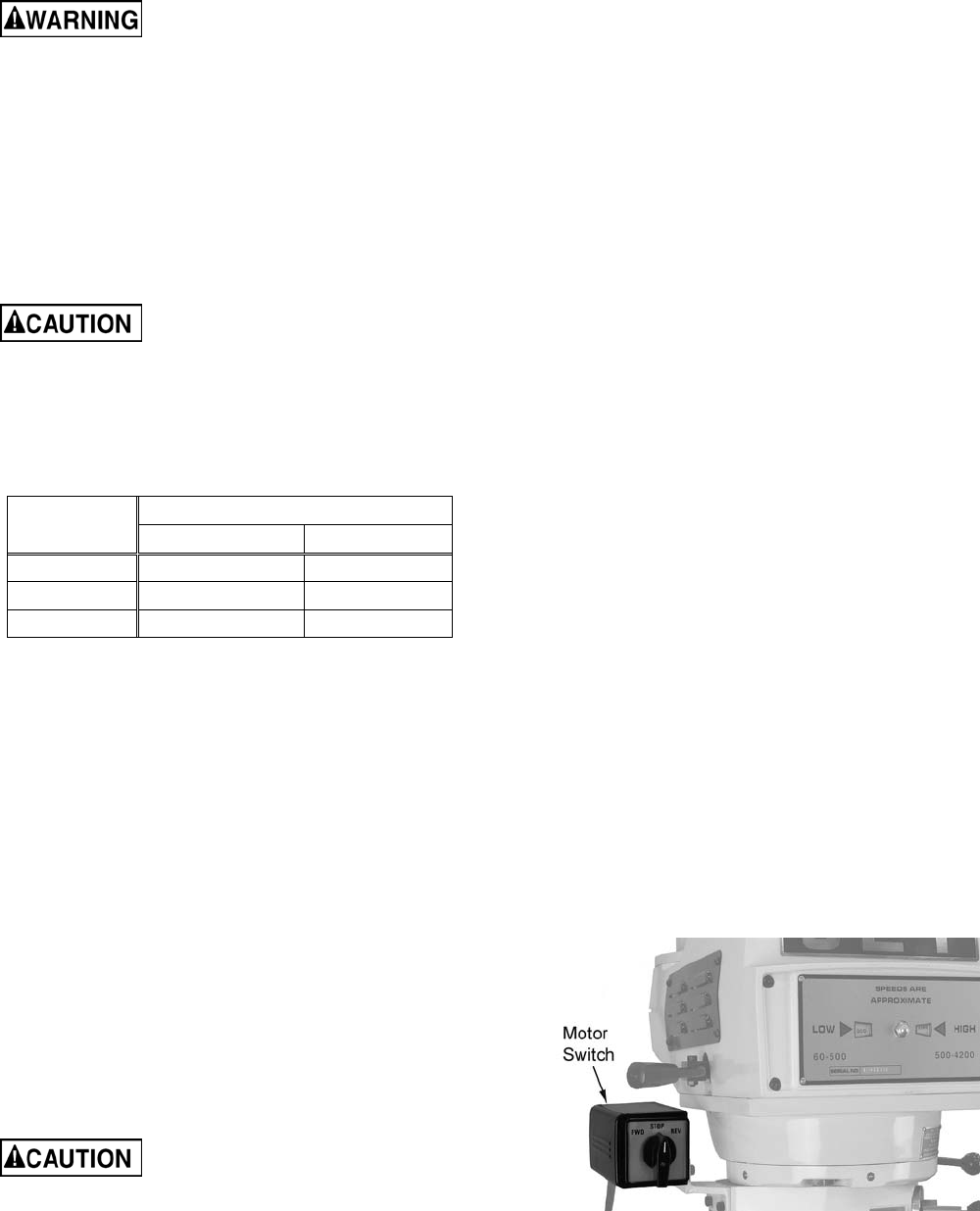
Motor Switch
The Motor Switch is on the upper left-hand side of the
mill head (Figure 5). The switch has three positions:
FWD (forward), STOP, and REV (reverse).
Setting the switch to FWD will provide clockwise
spindle rotation. Use FWD for normal, right-hand
tooling.
FWD (clockwise) operation occurs only when the
gearbox is in the low speed position. When the
gearbox is in high-speed position, the motor switch
must be in the REV position to provide right-hand or
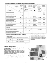
clockwise rotation. Refer to Figure 6 for a chart of
required switch positions.
The motor switch controls a three-phase motor. The
motor can be switched from FWD to REV and back
with the motor running, and will reverse direction
when the switch setting is changed. At higher
speeds, this may put strain on the timing belt but
there will be no damage to the motor or gear
mechanism.
Figure 5