


23
Replacement of Vari-Speed Belt
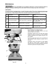
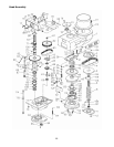
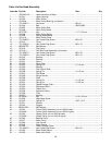
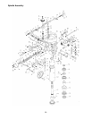
Refer to Figures 31 and 32, and Head Assembly in
the Parts section.
Disconnect electrical power to
the machine before performing any maintenance.
1. Remove drive motor (refer to the Replacement of
Drive Motor section).
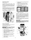
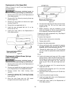
2. Remove Quill Top Cover by removing three cap
screws (Figure 31).
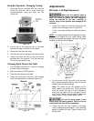
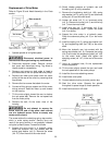
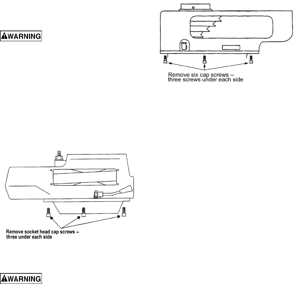
3. Remove six cap screws and remove the upper
housing (Figure 32).
4. Remove the vari-speed belt (ref. 4).
5. Install the new vari-speed belt (ref. 4) on the
driven hub (ref. 44).
6. Install drive motor (refer to the Replacement of
Drive Motor section).
Figure 32
Replacement of Brake Shoes, Springs
and/or Timing Belt
Disconnect electrical power to
the machine before performing any maintenance.
1. Remove drive motor (refer to the Replacement of
Drive Motor section).
2. Remove vari-speed belt and upper housing (refer
to the Replacement of Vari-Speed Belt section).
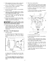
3. Remove screws from lower housing cover
(ref. 50).
4. Loosen the setscrew (ref. 3) securing the brake
pivot finger stud (ref. 58) in the lower housing
cover (ref. 50).
5. Move the pivot finger stud (ref. 58) inward
enough to remove the snap ring (ref. 60).
Figure 33
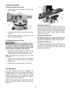
6. Pull the pivot finger stud (ref. 58) out of the lower
housing cover (ref. 50) and the brake pivot
fingers (ref. 59).
7. Before removing, note the orientation of the
brake pivot fingers (ref. 59) for correct positioning
for re-assembly. Remove the pivot fingers.
If replacing the brake components only, skip Steps 8
and 9 and go to Step 10.
To replace the timing belt:
8. Remove lower housing cover and pulley.
9. Replace belt (ref 63).
To replace the brake components:
10. Using a soft-faced mallet, tap upward to separate
the lower housing cover (ref. 50) and the brake
assembly (ref. 47) from the bearing (ref. 43).
11. Remove the brake shoes (ref. 47) and springs
(ref. 49). Install the replacement brake shoes and
springs.
For all:
12. Position the brake pivot fingers (ref. 59) as noted
during removal. Install the pivot finger stud (ref.
58) through the lower housing cover (ref. 50) and
into the brake pivot fingers (ref. 59). Install the
snap ring (ref. 60) on the pivot finger stud (ref.
58).
13. Tighten the setscrew (ref. 3) to secure the pivot
finger stud (ref. 58).
14. Install the brake assembly (ref. 47) on the lower
housing cover (ref. 50).
15. Secure the lower housing cover (ref. 50) with four
screws.
16. Install timing belt and upper housing.
17. Install vari-speed belt (refer to the Replacement
of Vari-Speed Belt section).
18. Install drive motor (refer to the Replacement of
Drive Motor section).