


22
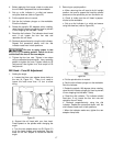
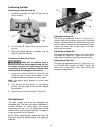
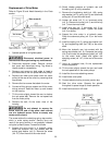
Replacement of Drive Motor
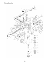
Refer to Figure 30 and Head Assembly in the Parts
section.
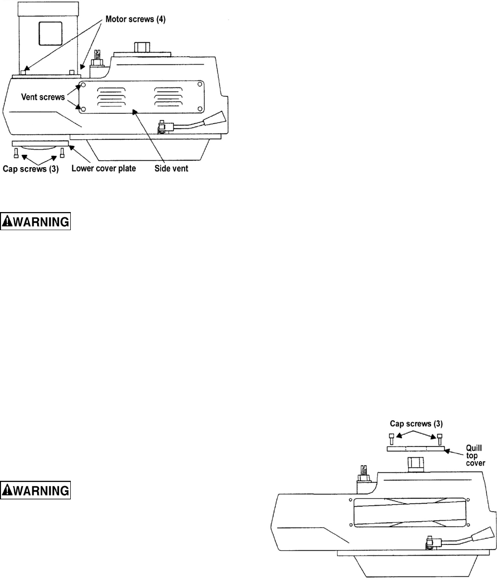
Figure 30
1. Operate spindle at its highest speed.
Disconnect electrical power to
the machine before performing any maintenance.
2. Disconnect electrical power. Remove junction
box cover and disconnect wiring. Tag wires to
identify leads for reinstallation.
3. Remove vent covers on both sides of head to
provide access to the vari-speed belt and pulleys.
4. Remove the lower cover plate under the motor
pulley (at the rear of the cover) by removing three
cap screws.
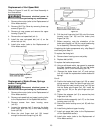
5. Remove the four screws that attach the motor.
6. Connect a lifting sling to support and lift the motor
during removal. Ease the motor up and forward
on the housing.
7. Tilt the motor slightly toward the rear to slacken
the vari-speed belt. Remove the vari-speed belt
from the motor pulley.
8. Remove the belt; lift the motor clear of the
housing.
Do not attempt to remove the
screw from the end of the motor shaft without
use of a hydraulic press. Failure to comply may
cause serious injury.
The screw retains the underlying spring stop washer,
which is under spring tension. Serious injury can
result if the spring tension is not gradually released
using the hydraulic press. Proceed as follows.
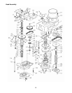
9. Support the drive motor in a hydraulic press.
Move the hydraulic ram into contact with the
spring stop washer (ref. 9). Remove the screw
(ref. 107) from the end of the motor shaft.
10. Slowly release pressure on hydraulic ram until
the spring (ref. 8) is fully extended.
11. Remove the lengthening shaft (ref. 106), spring
stop washer (ref. 9), spring (ref. 8) and outermost
pulley (ref. 5) from the motor shaft.
12. Loosen set screw (ref. 3) on innermost pulley
(ref. 2). Remove the pulley (ref. 2) and drive key
(ref. 7) from the motor shaft.
13. Install drive key (ref. 7) and pulley (ref. 2) on
shaft of replacement motor. Tighten set screw
(ref. 3) on pulley.
14. Support the drive motor in a hydraulic press.
Place the outermost pulley (ref. 5) on the motor
shaft.
15. Install the spring (ref. 8), spring stop washer (ref.
9), and lengthening shaft (ref. 106) on the motor
shaft.
16. Move the hydraulic ram into contact with the
spring stop washer (ref. 9). Compress the spring
(ref. 8) and install the lengthening shaft (ref. 106)
on the motor shaft. Install and tighten the
attaching screw (ref. 107) in the end of the motor
shaft.
17. Using an overhead hoist, lift the replacement
motor into position.
18. Tilt the motor slightly toward the rear and install
the vari-speed belt on the motor pulleys.
19. Install the four motor attaching screws.
20. Install lower cover plate.
21. Connect electrical wiring to motor junction box.
22. Start the drive motor. Operate the spindle
throughout its speed range to check operation.
23. Install vent covers on mill head.
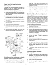
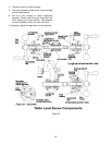
Figure 31