


17
4. Before applying final torque, check to make sure
the mill head is perpendicular to the worktable.
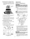
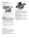
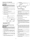
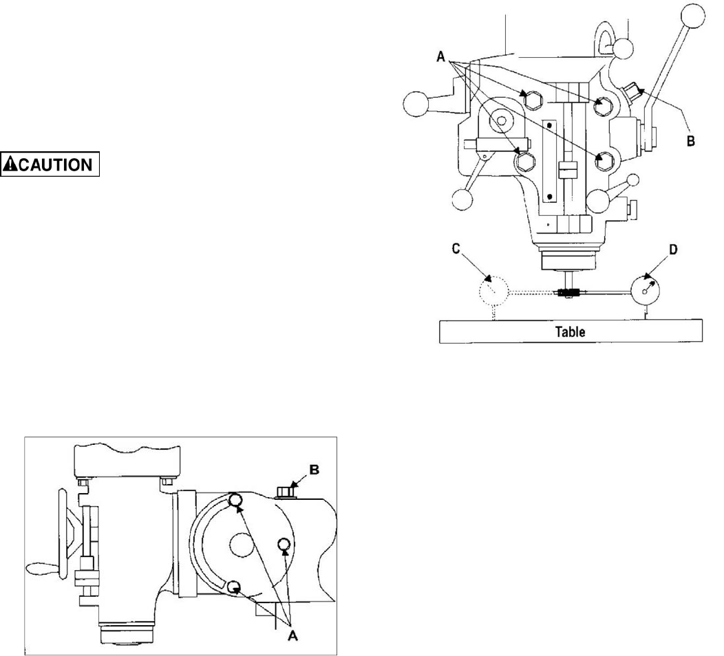
5. Set up a dial indicator in a collet and secure
using the draw bar (refer to Figure 22).
6. Put the spindle drive in neutral.
7. Set the dial indicator plunger on the worktable.
Zero the indicator.
8. Rotate the spindle 180 degrees (when rotating,
raise the dial indicator plunger by hand to prevent
it from dropping into the table T-slots).
9. Read the dial indicator. The indicator should read
zero. If not, loosen the four hex nuts and
reposition the mill head.
10. Recheck perpendicularity using the dial indicator.
Repeat the procedure above until the dial
indicator reads zero in both positions.
Be sure to apply torque in two
steps using a crossing pattern. Failure to do so
could distort the face of the ram adapter.
11. Tighten the four hex nuts. Tighten in two steps
using a calibrated torque wrench. Use a crossing
pattern to tighten the nuts. Tighten initially to 25
foot-pounds, then tighten to a final torque of 50
foot-pounds.
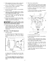
Mill Head – Fore/Aft Adjustment
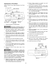
1. Setting the angle:
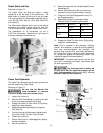
a. Loosen the three ram adapter clamp bolts on
the ram (A, Figure 21). There is no need to
loosen the bolts more than 1/2 turn to allow
tilting.
Figure 21
b. Support the mill head with your free hand.
Press upward on the spindle when changing the
angle.
c. Turn the ram adapter worm nut (B, Figure 21)
to tilt the head forward and backward. Use the
scale on the ram adapter to locate the desired
angle.
2. Returning to upright position:
a. When returning the mill head to its full upright
position, be sure to support the head by upward
pressure on the spindle as you turn the worm nut.
b. Check to make sure the mill head is perpen-
dicular to the worktable.
c. Set up a dial indicator in a collet and secure
using the draw bar (refer to Figure 22).
Figure 22
d. Put the spindle drive in neutral.
e. Set the dial indicator plunger on the worktable.
Zero the indicator.
f. Rotate the spindle 180 degrees (when rotating,
raise the dial indicator plunger by hand to prevent
it from dropping into the table T-slots).
g. Read the dial indicator. The indicator should
read zero. If not, loosen the four hex nuts and
reposition the mill head.
h. Recheck perpendicularity using the dial
indicator. Repeat the procedure above until the
dial indicator reads zero in both positions.
i. When the indicator reads zero, tighten the ram
adapter clamp bolts.