


8
Set-up and Installation
Preparing the Milling Machine for Service
1. Remove any crating which may be covering the
machine on the pallet.
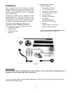
2. Remove accessory items from the pallet or
machine table. Compare these items with the list
on the previous page.
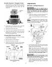
3. Check the tightness of the lifting ring on the ram
to be certain it is tight.
4. Check the tightness of the lock handles on the
ram (see Figure 23) to be certain the ram is
locked tight.
5. Remove the nuts and/or bolts, which secure the
machine to the pallet.
6. Center an overhead crane or other suitable
overhead lifting device and sling arrangement
over the lifting ring.
Note: This machine weighs over 2400 pounds!
Be certain the lifting arrangement is new or in
excellent condition and has a safety factor that
will account for age, difficulties in lifting, etc.
When lifting using the ring, the machine will tip
forward. If you wish, you can minimize this tipping
by rigging a support sling over the front of the
machine. Be careful when doing this, to prevent
the sling from damaging any components on the
front of the machine. Be sure to steady the mill to
prevent it from spinning.
7. Lift the machine off the pallet no higher than
necessary to clear the hold-down hardware, then
pull the pallet out of the way. Do NOT get hands
or feet underneath the machine when removing
the pallet!
8. Put the machine base over the hold-down system
where the machine will be spotted. Anchor bolts
of sufficient size and length must be fastened to
the floor according to the footprint of the mill. See
diagram on page 10.
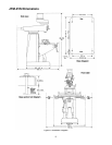
Note: The accompanying diagrams show you the
maximum dimensions of the machines with the
table, ram, etc., fully extended in all possible
directions. When spotting the machine be certain
to leave room not only for the machine itself, but
also for operator clearance and clearance for
workers servicing the machine, and any unusual
sizes of workpieces that might extend off the
machine’s table.
9. When the machine is over its anchors, level the
machine using shims under the corners needing
them. The machinist’s level used for leveling
should be placed on the table. The table is the
reference surface for both side-to-side and fore-
and-aft leveling. Be certain you get it level in
BOTH directions.
Mill must be supported equally
under all four corners. Failure to comply may cause
the column to twist and put a bind in the table ways.
10. When the machine is level, secure the base to
the anchor system.
IMPORTANT: Before attempting to raise the mill
head, refer to Mill Head – Left/Right Adjustment in
the Adjustments section for procedures to safely
raise and set up the mill head.
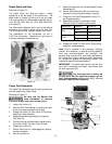
11. Loosen the four hex head nuts (see A, Figure 22)
about 1/4 turn each (counterclockwise), just
enough to allow rotation of the head.
12. While assisting the worm mechanism by putting
upward pressure on the motor by hand, use the
wrench supplied with the machine to turn the
worm nut and raise the head to upright position.
13. Tighten the headbolts slightly — not torqued —
just snug.
14. Using mineral spirits or other cleaning solvent,
clean all of the rust proofing from where it may
have been applied. This is important; moving the
table or any other components before removing
the rust proofing will only put rust proofing where
you don’t want it.
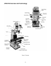
Some of the following steps may have already
been performed on the machine. If so, ignore the
instructions related to those particular steps.
Otherwise, perform them in the order listed,
referring to Figure 11 for any clarification.
15. Install the table traverse and cross-feed cranks
on their respective shafts using the nuts on the
shafts to secure the cranks.
16. Remove any rust proofing from the drawbar and
its washer, and put the drawbar with washer
installed into the spindle center through the top of
the machine.
17. Slide the fine feed handwheel over the
handwheel hub and push it back until its rollpin
engages the hole in the hub and the wheel is
flush with the hub surface.
18. Put the coarse feed handle on the feed shaft and
tap it lightly until its roll pin engages a hole in the
hub and it is flush against the hub surface.
19. Unwrap and clean the knee crank and install it on
its shaft.
20. Install the rubber way covers at front and behind
the table.