


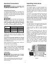
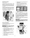
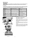
19
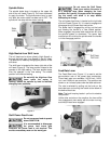
Power Feed Trip Lever Mechanism
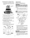
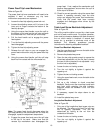
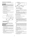
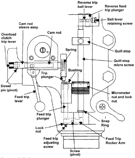
Refer to Figure 25.
The power feed trip lever mechanism will need to be
adjusted if worn or whenever any trip lever
mechanism components are replaced.
1. Loosen the feed trip adjusting screw lock nut.
2. Loosen the adjusting screw until it is loose in the
lever and no longer contacts the bottom of the
feed trip plunger.
3. Using the coarse feed handle, move the quill to
the bottom of its travel so the quill stop contacts
the micrometer nut. Hold the quill on the stop.
4. Pull the feed handle out to engage the power
feed system.
5. Turn the feed trip adjusting screw until the power
feed disengages.
6. Tighten the feed trip adjusting screw.
7. Release the quill stop so you can engage the
power feed mechanism using the power feed trip
lever.
8. Using the coarse feed handle, pull the quill stop
back into firm contact with the micrometer nut.
Figure 25
Note: The power feed should disengage when the
quill stop pushes on the micrometer nut. If it does not
disengage, repeat the adjustment steps above.
9. Engage the power feed and move the quill stop
to the top of its travel. Make sure that the
reverse trip mechanism also disengages the
power feed. If not, readjust the mechanism until
positive disengagement occurs when the quill is
at the top of its stroke.
10. Check for correct operation using the coarse feed
handle. If operating correctly, start the drive
motor and engage the power feed mechanism.
Verify that the power feed lever correctly
engages and disengages when driven by the
drive motor.
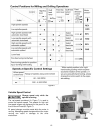
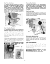
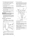
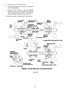
Table Lead Screw Backlash Adjustment
Refer to Figure 26.
The milling machine table is moved by a lead screw
and nut for each machine axis. For proper operation,
there must be clearance between the lead screw and
the nut, which results in backlash. A second lead
screw nut is provided to eliminate most of the
backlash. The following procedures provide
instructions for obtaining acceptable backlash.
Cross Feed Backlash Adjustment
1. Use the cross feed crank to move the table to the
extreme rear of its travel.
2. Remove the pleated way cover.
3. Open the two chip guards enough to expose the
cross-feed adjustment nut (the nut that is toward
the rear of the nut bracket is not adjustable – only
the front nut is adjustable).
4. Loosen the two nut locking screws.
5. Turn the nut slightly to tighten it against the
opposing nut.
6. Tighten the two nut locking screws.
7. Using the cross-feed crank, move the table to the
middle position.
8. Set up a dial indicator to check cross-feed
backlash. Gently move the cross feed crank back
and forth while watching the dial indicator.
Backlash should be between 0.003 inch and
0.005 inch.
9. If necessary, repeat the steps above to set
backlash.
10. Install the pleated way cover.
Longitudinal Backlash Adjustment
Refer to Figure 26.
1. Only one of the longitudinal lead screw nuts can
be adjusted. The other nut is fixed. The left hand
nut is typically adjustable. This can be
determined by looking at the nut from the
underside of the table.
2. Loosen the two nut locking screws.
3. Turn the nut slightly to tighten it against the
opposing nut.