


5. CONNECTOR INFORMATION
5.1 CONNECTOR PANEL
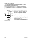
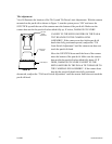
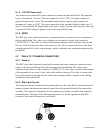
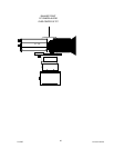
5.1.1 Lens I/F Connector: NOT USED JVC Configuration
The connector labeled “LENS I/F” on the connector plate is an eight mini DIN female (socket)
type. This connector provides signals to and from the camera lens in special applications.
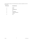
Internal wiring for this connector can be found on the MPU Module schematic diagram and is
directly wired to the 8 pin DIN connector located on the body of the pan & tilt. This is a
convenient location to monitor control signals to the lens during troubleshooting
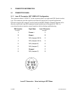
DIN Connector Signal Name Lens I/F Connector
Pin Number Pin Number
1 Focus + 1
2 Zoom + 2
3 N/A (Jumper 8 & 9) 3
4 N/A (Jumper 4 & 5) 4
5 N/A (Jumper 6) 5
6 N/A (Jumper 7) 6
7 Ground 7
8 N/A (Jumper 3) 8
Lens I/F Connector – View Looking at DPT Base
2/12/05 Document D0153
13