


5.1.2 Communications Interface
Control of the pan and tilt is accomplished by sending packets of ASCII characters to the head.
The standard communications protocol is 9600 baud, eight data bits, one stop bit , and no parity.
These commands tell the head and lens which direction and at what rate to move. Preset related
commands are also passed over the communication link between the head and the controller. In
most cases the communications link is either RS-422 or RS-232. The micro-processor in the pan
and tilt head will automatically detect the communication type being received, and select that
communication interface type to transmit data back to the controller. The pan and tilt also has the
provision to use both type interfaces concurrently for special purpose application
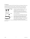
The RS-422 communications interface is also used to pass camera control commands to the
camera in the camera control mode (LDCC) for JVC cameras. In this mode the controller sends
the camera commands to the head in RS-422 format on the four wire cable. The commands are
received in RS-422 and converted to TTL levels by electronics in the head. These commands are
the sent out the RS-232 connector via the pan and tilt LDCC cable (P/N ACA96037900) to the
camera. These camera control commands enter the camera on the six pin mini-DIN “REMOTE”
connector on the rear panel of the camera
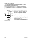
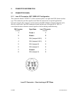
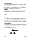
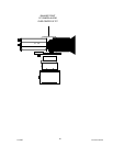
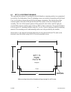
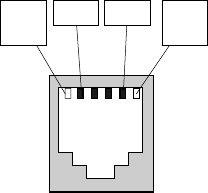
5.1.3 RS-422 Connector
The connector labeled “RS422” on the connector plate is a six position, four conductor modular
jack. This connector provides differential 0 to +5 VDC voltage signals to and from the digital
pan and tilt head, this is the most common interface from the controller to the heads. Shown
below is the pin-out for the RS-422 connector. The pin assignment for this connector follows:
Pin 2 Pin 5
Pin 6
Not
Used
Pin 1
Not
Used
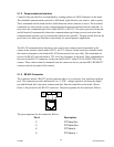
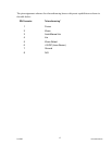
The pin assignment for this connector follows:
Pin # Description
2 P/T Data Out -
3 P/T Data Out +
4 P/T Data In -
5 P/T Data In +
2/12/05 Document D0153
14