


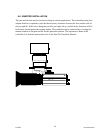
5.3 DPT JUMPER INSTALLATION.
It will be necessary to disassemble pan and tilt mechanism from base of DPT unit to gain access
to the configuration jumpers on the MPU PWA. The MPU PWA is the top board and will be
accessible as soon as the pan and tilt mechanism is removed. The following steps describe
reconfiguring the jumpers. The equipment necessary for this procedure are a No. 2 Phillips screw
driver a small pair of needle nose pliers and a 2” x 8” x 8” block of some type. Verify the DC
jack providing power to the unit has been removed prior to proceeding.
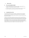
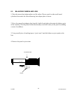
5. Position the pan and tilt at the parked or normal position. This position is defined as the
camera mounting plate being horizontal to the work surface and the two video BNC
connectors on the pan and tilt being on the same side facing the individual working on
the unit.
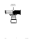
6. Remove the four Phillips head screws fastening the pan and tilt mechanism to the base.
7. Position the block directly behind the pan and tilt unit.
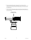
8. Remove pan and tilt mechanism by lifting slightly and rotating away from you, this step
will leave the pan and tilt mechanism laying on the side away from the BNC connector
behind the base.
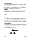
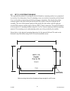
9. The three position jumper posts will now be accessible at the far left corner of the PWA.
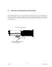
10. Place the pan and tilt mechanism back on the base.
11. Replace the four Phillips head screws fastening the pan and tilt mechanism to the base.
2/12/05 Document D0153
18