


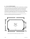
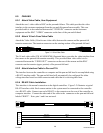
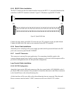
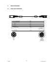

6.9.5 RS-232 Cable Installation.
The RS-232 cable provides the control interface between the DPT 115 pan and tilt head and the
controller if an RS-232 interface is desired. Figure 3-3 illustrates a typical RS-232 cable.
P2 P1
5
3
2
5
3
2
Red
White
Black
Black
Red
White
Black
Black
Figure 3-3: Typical RS-232 Cable
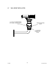
Connect the plug (male) end of RS-232 to the nine pin “D” connector on the pan and tilt head.
Connect the other end of the cable to the connector on the RS-232 controller.
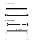
6.9.6 Power Cable Installation
Attach the power cord plug on the power supply provided with the pan and tilt head to the DC
jack on the connector panel labeled “POWER”.
6.9.7 Lens I/F Connector
This connector is not used for most applications. No connections should be made to this
connector during normal setup. In the event this connector is to be used a full description will be
provided in the application note for that particular configuration.
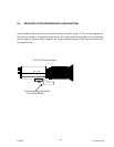
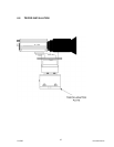
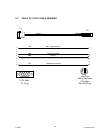
Lens Control Cable Installation
6.9.8.1 KY-F32 Configuration
Attach the 8-pin circular DIN male connector of the lens control cable (ACL99088000) to the 8-
pin female DIN on the trunnion of the pan and tilt. Attach the other end, a male Hirose connector
to the female Hirose on the teleconferencing lens.
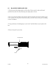
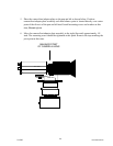
At this time there will be one cable on the teleconferencing lens not connected. Plug this male
Hirose connector into the female “LENS” connector on the rear of the KY-F32 camera.
2/12/05 Document D0153
29