


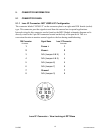
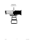
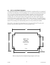
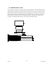
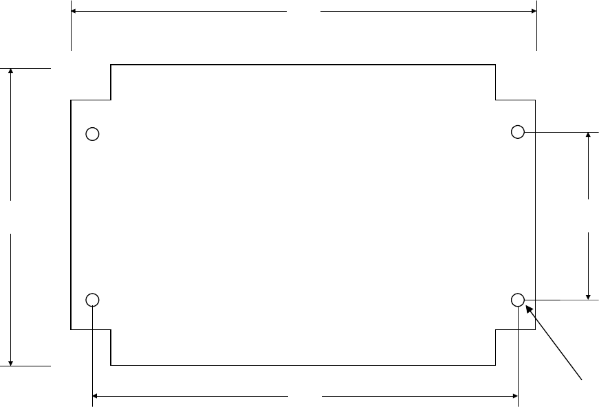
6.3 DPT 115 FOOTPRINT DRAWING
The required hole pattern for securing the pan & tilt head to a mounting surface is a symmetrical
two-inch by five-inch pattern. Four (4) mounting screws are needed to mount the pan & tilt head.
Care is to be taken to mount the pan & tilt in the proper orientation. Note the location of the
connector plate on the base of the pan & tilt head. This surface is the rear of the pan & tilt
assembly. The rear of the trunnion portion of the pan & tilt is the surface with the eight pin
circular DIN connector and the upper of the two BNC (Video) connectors. The pan & tilt head is
to be secured to it’s mounting location using No. 6 or No. 8 screws consistent with the mounting
material. The mounting screws and mounting surface are to be provided by the installer.
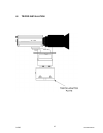
Shown below is the physical mounting dimensions for the pan and tilt head. The unit can be
fastened to any flat surface using #8 or #10 wood or machine screws.
5.50 in.
3.50 in.
1.95 in.
4.95 in.
DPT 115
Digital
Pan & Tilt
footprint
Make mounting holes without threads and large enough for a #10 screw
#10 Mounting
Holes 4 places
Front
2/12/05 Document D0153
21