


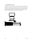
6.9 CABLING
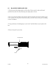
6.9.1 Attach Video Cable, User Equipment
Attach the user’s video cable to BNC on the pan and tilt base. This cable provides the video
interface to the customer equipment from the pan and tilt/camera/lens assembly. This user
provided cable is to be connected between the “VIDEO IN” connector on the customers
equipment and the BNC “VIDEO” connector on the base of the pan and tilt head.
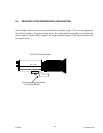
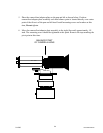
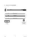
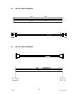
6.9.2 Attach 18 Inch Coax Video Cable
Attach the Video Cable (18 inch coax video cable) between the camera and the pan and tilt
trunnion connectors. The trunnion connector on the rotating section of the pan and tilt head.
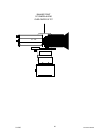
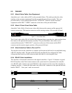
Figure 3-1: 18 Inch Video Cable
The 18 inch video cable (P/N ACA95018700) illustrated above provides the video interface from
the camera to the pan and tilt trunnion assembly. This provided short video cable is to be
connected between the “VIDEO OUT” connector on the rear of the camera and the BNC
connector on the trunnion (upper portion) of the pan and tilt head.
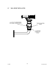
6.9.3 Attach Interface Cable to Pan and Tilt.
The interface between the controller or computer and the pan and tilt head is accomplished using
a RS-422 interface cable. The pan and tilt head will automatically be configured for either
voltage interface based on which connector and cable that it is receiving data from.
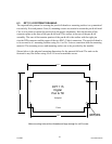
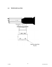
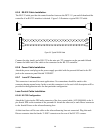
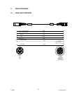
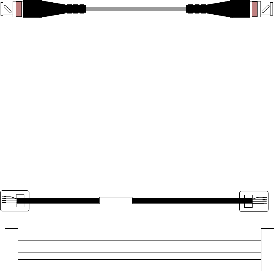
6.9.4 RS-422 Cable Installation.
This interface is the normal connection to the digital controllers. Figure 3-2 illustrates a typical
RS-422 interface cable. Each camera station in the system must be connected to the controller
via a RS-422 cable. Connect one end of RS-422 to the connector on the rear of the controller or
computer interface. Connect the other end of the cable to the connector on the pan and tilt head
labeled “RS422”. Note: pins 1 and 6 are not used.
ACA96037900
Black
Red
Green
Yellow
P/T Out -
P/T Out +
P/T In -
P/T In +
1
2
3
4
5
6
1
2
3
4
5
6
2/12/05 Document D0153
28