


27
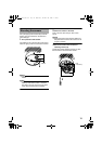
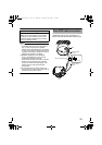
Connect the alarm input/output cables with
external devices such as a sensor, buzzer, etc.
Note:
● Noises from an external source may cause
malfunctions even when the cable used is
shorter than 50 m. In this case, use a
shielded cable or move the cable away from
the noise source.
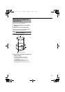
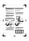
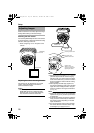
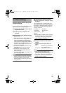
Alarm Input
Connect this terminal to sensor devices, such as
an infrared sensor, door sensor, metal sensor,
manual switch, etc.
Ⅵ Input requirements
● No-voltage relay NPN open collector input
● Polarity of input detection can be selected
using a software
● Make/Break (500 ms and above)
● Circuit current at low level: 0.3 mA
● Applied voltage at high level: 3.3 V
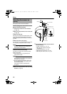
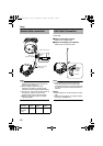
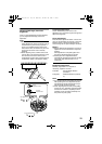
Alarm Output
Connect this terminal to annunciating devices, such
as annunciators, indicators, lights, buzzers, etc.
Ⅵ Output requirements
● Equivalent to NPN open collector output (Set
the output put logic via the Internet Explorer)
● Allowable applied voltage: DC12 V and below
● Allowable inflow current: 50 mA
● Momentary (100 ms to 5000 ms) output
(Set time via the Internet Explorer )
Note:
● Connect the GND cable of this camera to the
GND of the annunciating device.
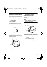
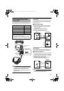
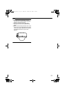
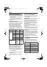
Alarm Input/Output Cable
Connection
Signal name Cable color
Alarm input 1 Pink
Alarm input 2 Blue
Alarm output 1 Orange
Alarm output 2 Yellow
GND Brown
Cable to use
● Length of 50 m or shorter
● UL1007, UL1015 or equivalent products
● AWG#22 - AWG#18 or equivalent products
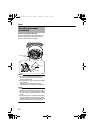
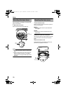
3
Solder or crimp
Insulation tape
Wind the
waterproof
tape
Alarm input/output
cables
LAN cable
DC3.3 V
R
3.3 V
0.3 mA
VCC
OUT
GND
GND
OUT
R
GND
(Alarm input equivalent circuit)
Input 1
or Input 2
Camera
unit
Sensor example (1)
Sensor example (2)
Relay switch etc.
IN
R
DC 12 V
GND
GND
Example of
annunciating
devices
Camera
unit
(Alarm output equivalent circuit)
Output 1
or Output 2
VN-C215VP_EN.book Page 27 Wednesday, December 20, 2006 4:26 PM