


[a] [b)
[c]
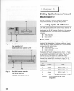
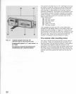
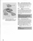
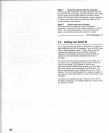
Fig. 3.5 SCSI connection
on
the
lS-10
Connexlon SCSI
du
lS-10
SCSI-Stecker
an
lS-10
36
Procedure
3.1 provides step-by-step
instructions
for
physically
installing
the LS-10 internal-
mount
scanner.
Please read through this chapter
before
the actual
installation of the
scanner
.
Procedure
3.1
__________
_
Installing the internal-mount scanner
into the drive bay
Step
1 Connect the SCSI
cable
to the
lS-10
Connect one end of the
flat
50-pin SCSI
cable
to the
50
-pin SCSI connector on the
rear
of the LS-
10
as shown
in
Figure
3.5. Insure that Pin 1 of the
cable
is
aligned
with Pin 1
of
the
scanner
.
[a] LS-10
rear
side
[b] SCSI connector
(c] SCSI
flat
cable
(SCSI
cable
showing
keying)
The connectors on both the
scanner
and on the
cable
are
protected with a
protruding
tab to
force
the
connector to
mount
properly
. Note that Pin 1 on the
scanner
connector and the
cable
connector
is
marked
with a
triangle
, and the
wire
associated with Pin 1 has a
red
str
ipe on it. Do not force the
cable
connector
into the
scanner
. It should
snap
into place with a
bit
of
force
. Be
careful to have the
connector
on the
cable
positioned
parallel
to the connector on the
scanner
before
applying
force. This
will
reduce the risk
of
bending
any
pins
.
Warnlngl
Make sure
Pin
1 marked on the scanner connector
mates with Pin 1
of
the flat cable connector.
Step
2 Terminating the SCSI
LS
-
10
needs the SCSI
termination
. Refer to " 3-4
Terminating
the SCSI chain" in
this
chapter
for
more
information.
Step
3
loosen
the lock down screws
On one
or
both
sides
of the
drive
bay
opening
are
locking
screws
. These may be positioned so that they
block the access to the
openings
in the
drive
bay
where
the
rails
will
slide
in. Loosen these
screws
so that the
metal tab does not block access to the
openings
. It
may
be necessary to
remove
these tabs. Keep them
handy
because they
will
be repositioned in Step 6
below
.