


~14----[a]
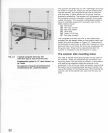
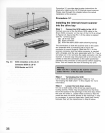
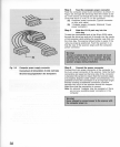
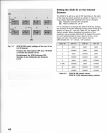
Fig. 3.6 Computer power supply connector
Connecteurs d'alimentation d'unite centrales
Stromversorgungsstecker des Computers
38
Step
4 Feed the computer
power
connector
Feed the
computer
power
4-pin
connector
, as shown in
Figure 3.6, through the
drive
bay from the
inside
as
far
as
it
will
extend out through the
drive
bay
. Connect
the
cords with each
12
V
DC
or
5 V
DC
connector
.
[a]
Computer
power
connector (Typical
connector
on
four
wire
cable)
[b] V-Adapter
power
connector (Optional V-type
power
connector)
Step
5 Slide the LS-10 part way Into the
drive bay
Thread the unconnected end of the 50-pin SCSI
cable
through the
drive
bay
and pull
it
through into the
inside
of
the
computer
while
sliding
the
scanner
rear-first
into
the
drive
bay
. The
scanner
should
slide
in
easily
if the
rails
are
properly
positioned. Push the
scanner
in
so
that the
rear
of the
scanner
aligns
with
the
computer
power
connector.
Warnlngl
The top or
boHom
of
the scanner should not touch
anything when sliding Into the computer. Damage
can occur
to
the scanner or
to
other devices If the
scanner scrapes during Installation.
Step
6 Connect the power connector
Connect the 4-pin
power
connector
of the
computer
to
the 4-pin
power
connector
of
the scanner. Note that both
connectors
are
keyed so that one
side
of
the connector
is beveled.
Be
careful to
insure
that the beveled edges
are
properly
aligned. Under
certain
circumstances,
it
is
possible
to
force
the connector in
at
an
improper
angle
thereby
creating
a backward connection.
Extreme
damage
can
occur
to the
scanner
should
this happen.
Make
sure
that the connection is correct.
Note: An optional V-adapter
may
be
necessary
if
there
are
not any
available
power
connectors in the
computer
.
Warnlngl
Never aHempt
to
connect power
to
the scanner
with
the computer power
on.