


– 8 –
3
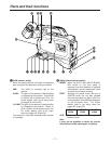
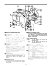
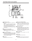
OUTPUT selector switch
CAM: The video signals shot by the camera
are output.
BAR: The color bar signals are output.
4
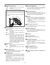
SHUTTER switch
This is the ON/OFF selector switch of the
electronic shutter.
OFF: The electronic shutter does not work at
this position.
ON: The electronic shutter is operational at
this position.
SELECT:This position is used to change the
speed of the electronic shutter. This is a
non-locking switch. Each time it is
operated, the shutter speed changes by
one setting in the following sequence:
1/100 1/125 1/250 1/500 1/1000
1/2000 1/4000 1/8000. When the
switch is operated at 1/8000, the speed
returns to the 1/100 setting.
5
POWER switch
ON: All the functions of the camera VTR are
made operational.
OFF: The power to the camera VTR is turned
off.
6
MODE CHECK switch
This enables the settings of the camera’s function
switches to be checked in the viewfinder.
7
BREAKER switch
If trouble causes an excessively high current to
flow inside the unit, the circuit breaker is tripped,
causing the power to be turned off automatically to
protect the unit.
Upon completion of inspection inside or repair
work on the unit, push this button to the “in”
position. The power will be turned on again
provided that no trouble has occurred.
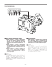
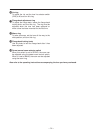
8
Earphone (PHONE) jack
This is the earphone (stereo) jack for monitoring
the sound. When an earphone is connected, no
sound will be heard from the speaker.
:
Speaker
The sound can be monitored through this speaker.
O
The sound from the speaker is automatically cut
off when an earphone is connected to the
PHONE jack.
O
The CH1 and CH2 sound is mixed and heard as
the monitored sound.
;
Audio monitor level control
This volume control is used to adjust the sound
when it is being monitored.
<
MARK/CANCEL button
This is the SCENE data function switch. For
further details, refer to the SCENE data function
section (on pages 56 and 57).
9
Audio input connectors
External microphones are connected here. Line
input signals can also be connected by setting an
internal switch to the corresponding position.
=
Viewfinder
>
Shoulder belt fitting
The shoulder belt is fastened here.
?
External DC input socket
This socket is for the external power (DC) supply.
Connect an AC adaptor.
When the adaptor is connected, power is
automatically supplied from the external power
source.
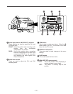
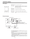
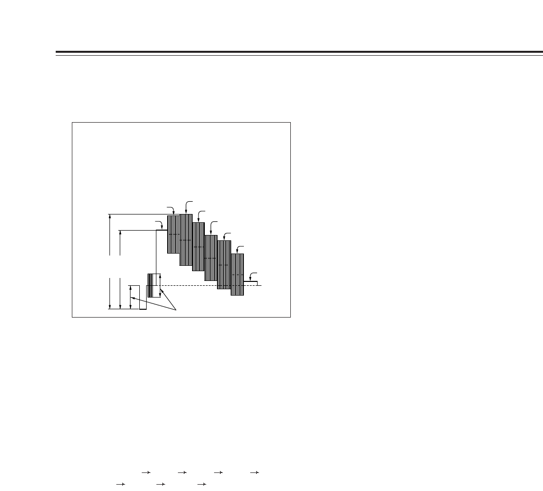
<Note>
Shown in the figure below are the output levels
which are shown as color bar signals by this
unit.
It should be noted that these are not SMPTE
color bars.
1.15 V
1.0 V
White
Yellow
Cyan
Green
Magenta
Red
Blue
Black
0.286 V
A
DVCPRO interface connector installation area
(option)
@
ND filter ON/OFF switch
OFF: The ND filter is not used.
ON: The ND filter is used.