


C2910M-A (4/05) 13
USING THE MULTIFUNCTION CONNECTOR
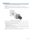
The CCC5100H Series camera combines data, video, and power leads into a single multifunction connector on the rear panel. This lets you
quickly install and uninstall the camera.
The camera supports two different RJ-45 plugs, depending on the application. Use a 10-pin RJ45-10 plug. (The 10-pin RJ45-10 plug is also
known as an RJ-50 plug.) If you will not use camera control to access the on-screen menus, you can use an 8-pin RJ-45 plug.
To install the multifunction connector, you will need the following:
•
Unshielded twisted pair cable, either 10-conductor in five twisted pairs or 8-conductor in four twisted pairs. If you will not implement UTP
video, you can use flat Cat5 or Cat6 cable.
•
RJ45-10 (10-pin) or RJ-45 (8-pin) plugs
•
A crimping tool that matches the plug type: RJ45-10 (10-pin, 10-conductor) or RJ-45 (8-pin, 8-conductor)
Next, identify the multifunction connector leads that you will use.
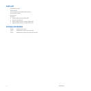
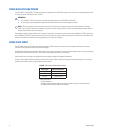
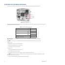
Wire the cable and connectors according to Table C. Figure 5 identifies pin 1 on the multifunction connector.
Finally, plug the multifunction connector into the camera. Each pair of leads is described in more detail in
Control Leads, Coax Video Leads,
Unshielded Twisted Pair (UTP) Leads,
and
Power Leads.
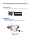
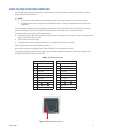
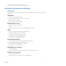
Table C.
Multifunction Connector
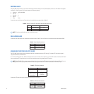
Figure 5.
Multifunction Connector, Pin 1
NOTES:
•
Do not connect a network cable into the multifunction connector on the camera’s rear panel. It is
not
a network connector.
•
The PCM150 camera mount is designed for the CCC5100H Series camera. It includes a preconfigured cable and an easy-to-wire
adapter plate.
By Pin By Pair
Pin Lead Pin Lead
1 Pelco Data RX+ 1 Pelco Data RX+
2 Coax Video Return 10 Pelco Data RX-
3 Coax Video 3 Coax Video
4 Reserved 2 Coax Video Return
5 UTP- Video 6 UTP+ Video
6 UTP+ Video 5 UTP- Video
7 Reserved 9 12 V / 24 V
8 GND / 24 V 8 GND / 24 V
9 12 V / 24 V 4 Reserved
10 Pelco Data RX- 7 Reserved
PIN 1