


14 C2910M-A (4/05)
CONTROL LEADS
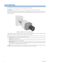
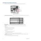
The CCC5100H Series camera lets you access and configure the menu settings from any Pelco keyboard, receiver, or other device that supports
the Pelco D or Pelco P protocol. The camera supports the following settings:
•
Baud rate: 2400, 4800, 9600
•
Start bit: 1
•
Data bits: 8
•
Stop bit: 1
•
Parity: None
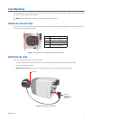
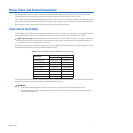
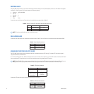
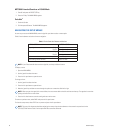
Connect the control wires from the Pelco device to the multifunction connector (refer to Table D).
Table D.
Device Transmit (TX) to Camera Receive (RX) Connections
COAX VIDEO LEADS
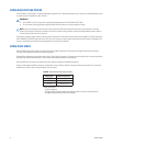
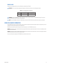
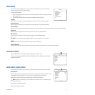
Connect the coax video wires to the multifunction connector (refer to Table E). Refer to Table B for the maximum video cable distance (BNC).
Table E.
Coax Video Connections
UNSHIELDED TWISTED PAIR (UTP) LEADS
The CCC5100H Series camera supports composite video over unshielded twisted pair (UTP) cabling. The camera UTP video output signal is
1 Vp-p differential into a 100-ohm load.
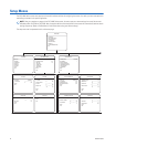
At a minimum, UTP requires Cat5, 100-ohm twisted pair cable. You can install either a passive or an active UTP receiver at the head-end. Table F
lists the maximum UTP wiring distances. It also lists the restrictions when using either type of UTP receiver.
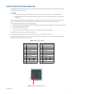
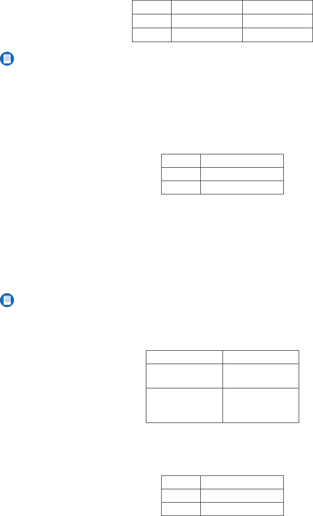
Table F.
UTP Wiring Distances
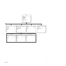
Connect the UTP video wires to the multifunction connector (refer to Table G).
Table G.
UTP Video Connections
Pin Lead Pelco Device
1 Pelco Data RX+ TX+
10 Pelco Data RX- TX-
NOTE:
To use the control leads, you must use an RJ45-10 plug.
Pin Lead
2 Coax Video Return
3 Coax Video
NOTE:
The CCC5100H Series camera supports video to both active and passive UTP receivers. However, Coaxitron and Pelco V-Sync are
only supported when using a passive UTP receiver. Refer to
Using Coax Video
for information about Coaxitron and Pelco V-Sync.
Receiver Distance
Active
(Video Only)
0-3,000 ft
(0-914.4 m)
Passive
(Video, Coaxitron,
Pelco V-Sync)
0-750 ft
(0-228.6 m)
Pin Lead
5 UTP- Video
6 UTP+ Video