


C2910M-A (4/05) 15
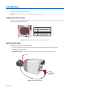
POWER LEADS
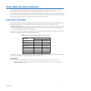
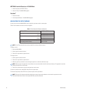
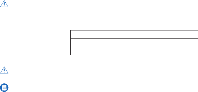
Connect the low voltage power wires to the multifunction connector (refer to Table H).
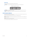
Table H.
Low Voltage Power Connections
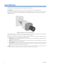
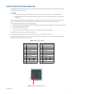
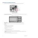
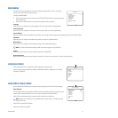
USING THE SERVICE CONNECTOR
The CCC5100H Series camera rear panel includes a service connector that outputs camera video and gives access to the setup menus. Use it to
configure the camera quickly and easily at the installation site.
Pelco offers two camera setup tools that plug into the service connector on the CCC5100H Series camera.
CST150:
This tool has top, center, and bottom buttons that operate like the three rear panel camera buttons. It also has a microdisplay to show
video directly from the camera.
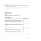
CST100:
This tool has top, center, and bottom buttons that operate like the three rear panel camera buttons. It also has a video output connector
to show video directly from the camera on a separate monitor.
You can use either tool to configure the CCC5100H Series camera with only one hand.
WARNING:
Do not connect high voltage power through the multifunction connector or you may damage the camera.
Pin 12-36 VDC
±10%
24-28 VAC
±10%
8 GND LO
9 Power HI
WARNING:
On the CCC5100H-6/CC5110H-6, apply power to either the power connector or the multifunction connector. The camera
cannot accept power at both connectors at the same time.
NOTE:
On the CCC5100H-7/CCC5110H-7 (120/240 VAC), pins 8 and 9 (12 VDC/24 VAC) on the multifunction connector are disabled.