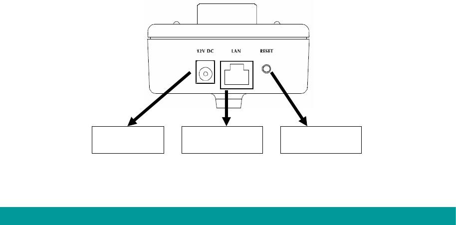
4.2. Hardware Connection
y Power Input
The DC power input connector is located on the IP Camera's bottom panel, and is
labeled 12V DC with a single jack socket to supply power to the IP Camera. Power will
be generated when the power supply is connected to a wall outlet.
y Ethernet Jack
The IP Camera's bottom panel features an RJ-45 connector for connections to
10Base-T Ethernet cabling or 100Base-TX Fast Ethernet cabling (which should be
Category 5 twisted-pair cable). The port supports “Auto-MDIX” function, allowing the
IP Camera to automatically detect or negotiate the transmission speed of the network.
For ICA-107P, this port is also the PoE interface.
y Antenna Connector (ICA-107W only)
ICA-107W provides a standard Reverse SMA connector on its top panel. The external
antenna allows you to adjust its position to obtain the maximum signal.
y Reset Button
1. Press the reset button (for less than 2 seconds) and the IP Camera will reboot.
2. Press the reset button for more than 5 seconds and the IP Camera will reset to the
factory default. The factory default settings are listed in the table below.
Ethernet Jack Power Input Reset Button
Bottom View of IP Camera
(Example on ICA-107)
Factory Default Setting
IP Address 192.168.0.20
Default Account Admin
Default Password Admin
Default Http Port 80
Default Video Port 4321
5


