


Appendix A
Alarm I/O Connector
Appendix A Alarm I/O Connector
Some features of the Network Camera can be activated by an external sensor that
senses physical changes in the area Network Camera is monitoring. These changes
can include intrusion detection or certain physical change in the monitored area. For
examples, the external sensor can be a door switch or an infrared motion detector.
These devices are customer provided, and are available from dealers who carry
surveillance and security products. Electrically, they must be able to provide a
momentary contact closure.
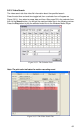
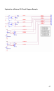
This Network Camera provides a general I/O terminal block with two digital inputs and
two outputs for device control. Pin 1 and 2 can be connected to an external sensor 1.
Pin 2 and 3 can be connected to an external sensor 2. Both of the inputs, the voltage
will be monitored from the initial state ‘LOW’. The relay switch of pin 4, 5 and 6 can be
used to turn on or off the external device. The relay switch of pin 7 and pin 8 can be
used to turn on or off the external device. External Inputs/Outputs are working
independently.
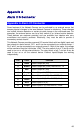
Pin Color Function
1 Black
Alarm Output #2 (NO)
2 Brown
Alarm Output #2 (COM). Max 24VDC, 1A
3 Red
Alarm Output #1 (NO)
4 Orange
Alarm Output #1 (COM)
5 Yellow
Alarm Output #1 (NC). Max 24VDC, 1A
6 Green
Alarm Input #2 (A). Max 24VDC, 12mA
7 Blue
Alarm Input #1/2 (K).
8 Purple
Alarm Input #1 (A). Max 24VDC, 12mA.
66