


LDK 8000 HDTV camera system User’s Guide (v3.0) 101
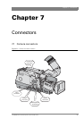
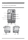
Chapter 7 - Connectors
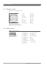
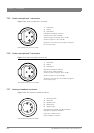
7. 2 . 8 DC power input socket
Caution
The input voltage must not exceed +17 Vdc.
Figure 7-13. DC power input connector
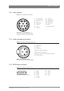
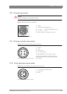
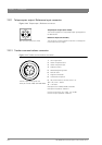
7. 2 . 9 DC power and tally output socket
Figure 7-14. DC power and tally output connector
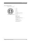
7. 2 . 1 0 Script light power supply socket
Figure 7-15. Script light power supply output connector
4
1
2
3
1. Ground
2. Ground (internally bridged to pin 1)
3. +11.5 Vdc . . . +17 Vdc (internally bridged to pin 4)
4. +11.5 Vdc . . . +17 Vdc
This socket accepts a DC voltage of 15V nominal.
XLR 4-pin male: panel view (X101)
4
1
2
3
1. Ground
2. On air
3. No connection
4. +12 Vdc (max. 18W)
Shield of cable directly to the connector housing.
The socket provides access to an internal tally switch.
When the camera is on-air, the contact of the internal
relay is closed.
Hirose 4-pole female: panel view (X110)
3
1
2
1. +12 Vdc (maximum dissipation 3W)
2. Power return
3. Shield
Fischer 3-pole female: panel view (X111)