


7
Chapter 7 Location and Function of Parts and Controls 119HDC-900/950/930 Series Product Information Manual
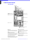
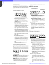
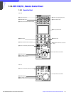
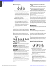
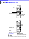
a Control select block
A PARA (parallel mode) button
This button lights when Parallel mode is active,
in which concurrent operation with another
control panel is possible. When this button is lit,
all the buttons and controls on this panel except
for the iris/master black control block are active,
even if the PANEL ACTIVE button is not lit. If you
press the button when lit, it goes dark and
Parallel mode is cancelled.
B MASTER and SLAVE buttons
When adjusting the white balance of multiple
cameras in Master/Slave mode, designate the
master camera or the slave cameras. Press and
light up the MASTER button to specify the
connected camera for the master. Press and
light up the SLAVE button to specify the
connected camera for the slave. The slave
cameras follow the master camera settings. If
you press a button when lit, it goes dark.
b STANDARD button
When you press this button, the video camera is
initialized to its standard state and the button lights for
several seconds. If you press the button while it lights,
the video camera reverts to the state before the button
was lit.
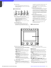
c Camera/CCU function ON/OFF buttons
Various functions of the video camera or the CCU/
HDCU-series can be turned on and off from this panel.
5600K: 5600K -electronic color temperature
conversion function
AUTO KNEE: Auto knee function. When this button is
lit (ON), the knee point is automatically adjusted
according to the light content of the picture.
SKIN DETAIL: Skin tone detail function
DTL GATE: Skin tone detail gate function. When this
button is lit (ON), the adjustment range of the skin
tone detail is displayed in white on the PIX (picture)
monitor screen.
BLACK GAMMA: Black gamma function
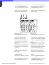
CHARACTER: Self-diagnostic display function. When
this button is lit (ON), the contents of the self-
diagnosis of the CCU/HDCU-series are displayed
on the monitor connected to the CHARACTER
OUTPUT connector of the CCU/HDCU-series. The
contents are also mixed to the video signal to be
output from the PIX1 OUTPUT connector. Each time
you press this button, the status changes as follows.
OFF t ON (page 1) t ON (page 2) . . .
t ON (page n) t OFF
The contents of the self-diagnosis may be displayed
when required even if this button is not lit. The right two
buttons are for future use and do not function at
present.
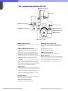
d WHITE (white balance manual adjustment)
knobs
Used to manually adjust the white balance. From the
left, the knobs are for R, G, and B signal adjustment.
e BLACK/FLARE (black balance/flare balance
manual adjustment) knobs and indicator
Used to manually adjust the black balance (when the
indicator is not lit) or the flare balance (when the
indicator is lit). From the left, the knobs are for R, G,
and B signal adjustment. Selection between black
balance and flare balance is made using the
Maintenance menu.
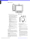
f Camera number/tally indication window
The number of the camera being controlled from this
panel is displayed in orange. When a red tally signal is
sent to the camera, the number is displayed in black
and the background of the number lights in red.
When a green tally signal is sent to the camera, the
number is displayed in black and the background of
the number lights in green. When both the red and
green tally signals are simultaneously sent, the left half
of the background lights in red and the right half lights
in green.
g ALARM indicator
Lights when trouble occurs in the camera system and
the self-diagnostic function activates at the video
camera or the CCU/HDCU-series.
h CALL button
Press to send a call signal to the video camera, on
which the CALL button lights. The tally lamps on the
camera and the red tally lamp on the CCU/HDCU
Series light when not lit, or go dark when lit. When the
CALL button on the video camera is pressed, the CALL
button on this panel lights and a buzzer sounds.
i PANEL ACTIVE button
Press and light up the button to permit this panel to
control the camera system (Panel active status). The
IRIS/MB ACTIVE button also lights. If you press this
button so that it goes dark, the panel will be locked,
preventing accidental misoperation.
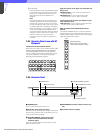
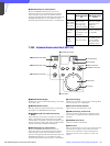
j Power and output signal select block
A CAM PW (camera power) button
Press and light up this button to turn the power
supply to the video camera ON. (The button
promptly flashes until the camera becomes
ready for transmission.) When you press this
button again, it starts flashing and the power
supply is turned off.
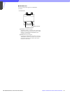
B Signal output select buttons
Press and light up one of these buttons to
activate the test signal generator of the video
camera and send the respective signals.
TEST: To send a signal to test the video circuits
BARS: To send a color bar signal
Note
The BARS button takes priority to the TEST
button. If the BARS button is lit, press the button
to turn it dark before pressing the TEST button.
PARA MASTER SLAVE
12
CHAR
ACTER
5600K AUTO
KNEE
SKIN
DETAIL
DTL
GATE
BLACK
GAMMA
CAM PW TEST BARS CLOSE
12 3