7
Chapter 7 Location and Function of Parts and Controls 123HDC-900/950/930 Series Product Information Manual
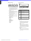
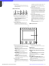
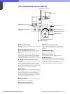
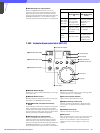
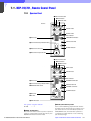
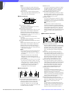
j Iris gauge
The white line on the gauge provides a click position
for the IRIS control. Turn the gauge to set the line to the
most frequently used iris position, and it can be used
as the reference for manual iris adjustment. The gauge
rotates infinitely in either direction. When no click
position is required, set the line outside the rotation
range of the IRIS control.
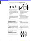
k AUTO button
Press and light the button to automatically adjust the
iris according to the amount of input light. When this
button is lit, the reference value for automatic iris
adjustment can be set in a range of ±1f with the iris
control. If you press the button when lit, it goes dark
and manual iris adjustment is enabled.
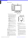
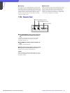
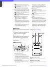
7-10-4 Connector Panel
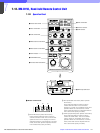
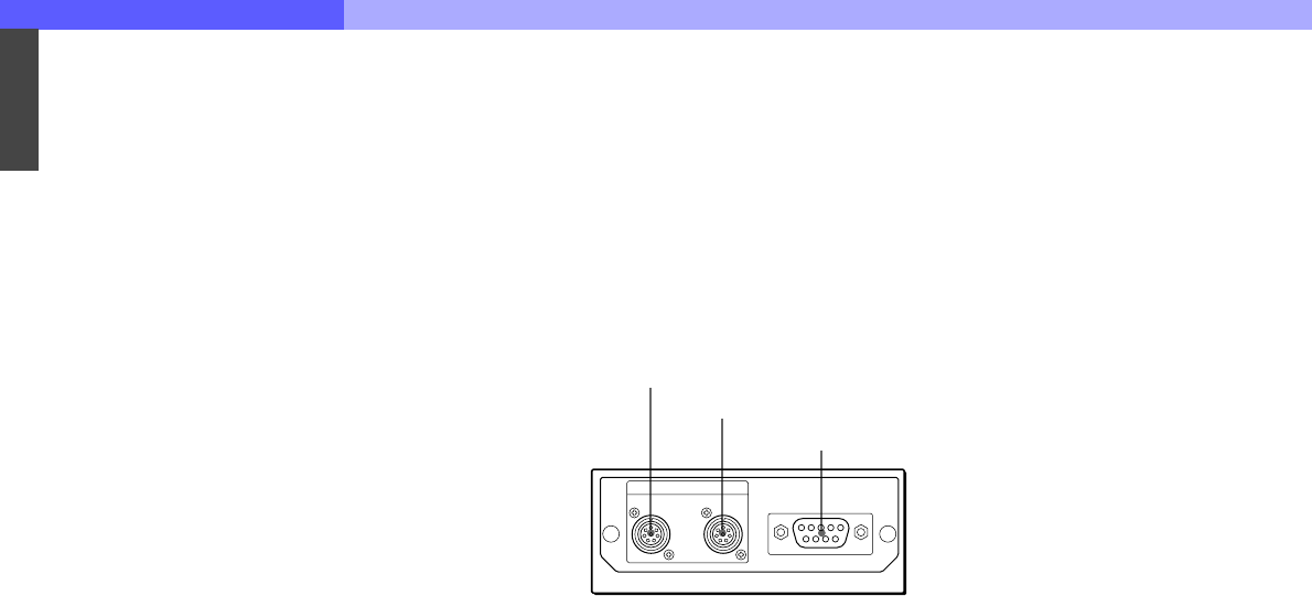
a CCU/CNU REMOTE (camera control unit/camera
command network unit remote) connector (8-
pin)
Connect to the RCP/CNU connector of a camera
control unit or the RCP connector of a camera
command network unit.
b AUX REMOTE (auxiliary remote) connector (8-
pin)
Connect to the RCP-700/701.
c EXT I/O (external input/output) connector (9-pin)
With expansion functions added, this connector
permits you to control an external device.
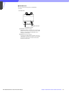
Caution
When installing this panel, provide a gap of 7 cm (3
inches) or more behind the connector panel to prevent
damage to cables.
1 CCU/CNU REMOTE connector
2 AUX REMOTE connector
3 EXT I/O connector
REMOTE
CCU/CNU AUX EXT I/O


