


24
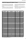
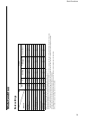
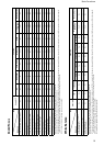
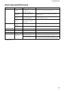
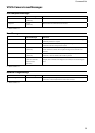
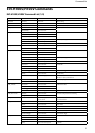
Command List
VISCA Communication
Specifications
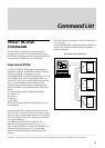
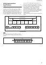
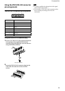
VISCA packet structure
The basic unit of VISCA communication is called a
packet (Fig. 2). The first byte of the packet is called the
header and comprises the sender’s and receiver’s
addresses. For example, the header of the packet sent to
the EVI-H100S/H100V assigned address 1 from the
controller (address 0) is hexadecimal 81H. The packet
sent to the EVI-H100S/H100V assigned address 2 is
82H. In the command list, as the header is 8X, input
the address of the EVI-H100S/H100V at X. The header
of the reply packet from the EVI-H100S/H100V
assigned address 1 is 90H. The packet from the
EVI-H100S/H100V assigned address 2 is A0H.
Some of the commands for setting EVI-H100S/H100V
units can be sent to all devices at one time (broadcast).
In the case of broadcast, the header should be
hexadecimal 88H.
When the terminator is FFH, it signifies the end of the
packet.
Bit 7
(MSB)
Bit 6 Bit 5 Bit 4 Bit 3 Bit 2 Bit 1 Bit 0
(LSB)
1 0
FF
Bit 7
(MSB)
Bit 6 Bit 5 Bit 4 Bit 3 Bit 2 Bit 1 Bit 0
(LSB)
1 1 1 1 1 1 1 1
Packet (3 to 16 bytes)
Message (1 to 14 bytes)Header
Terminator
Byte 1 Byte 2 Byte 3
Sender’s
address
Receiver’s address
Fig. 2 Packet structure
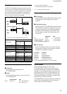
Note
Fig. 2 shows the packet structure, while Fig. 3 shows
the actual waveform. Data flow will take place with the
LSB first.
Bit 0 Bit 1 Bit 2 Bit 3 Bit 4 Bit 5
(LSB) (MSB)
Bit 6 Bit 7
Start
bit
Stop
bit.
1 byte
Fig. 3 Actual waveform for 1 byte.