


14
Locations and Functions of Parts
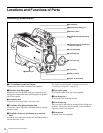
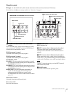
Pressing the left button selects the available ND filters
(clear, 1/4ND, 1/8ND, 1/16ND,1/64ND) in sequence.
Pressing the right button selects the available CC filters
(cross, 3200K, 4300K, 6300K, 8000K) in sequence.
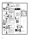
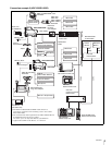
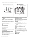
HDC1400R/1450R
You can switch the built-in optical filters (clear, 1/4ND,
1/16ND,1/64ND, cross) by pressing either of these buttons
while holding the FILTER LOCAL button depressed.
e FILTER LOCAL button
While holding this button depressed, press either of the
filter select buttons to select the built-in optical filters.
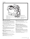
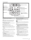
f AUTO W/B BAL (white and black balance
automatic adjustment) switch
To automatically adjust white and black balance when the
camera is used in standalone status without connecting to
the camera control unit.
WHT: Automatically adjust white balance.
BLK: Automatically adjust black balance.
g GAIN switch
To select the gain of the video amplifier based on lighting
conditions when the camera is used in standalone status
without connecting a camera control unit.
When shipped from the factory, the values set are L = 0 dB,
M = 6 dB, and H = 12 dB.
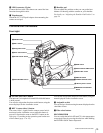
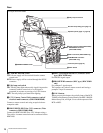
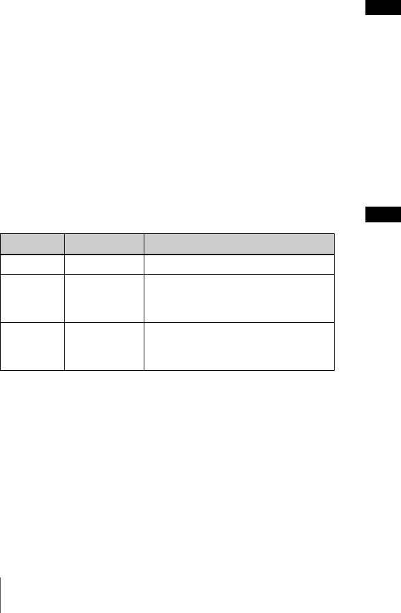
h OUTPUT (output signal selection)/AUTO KNEE
switch
To select the signal (color bar signal or camera’s video
signal) to be used as output to a VTR, the viewfinder or a
video monitor when the camera is used in standalone status
without connecting a camera control unit.
When the camera’s video signal is being used as output,
the auto knee function may be used.
The relationship between the switch setting and the output
signal and auto knee function is shown in the table below.
i WHITE BAL (white balance memory selection)
switch
To select the white balance adjustment method or the
memory used to store the adjusted value when the camera
is used in standalone status without connecting a camera
control unit.
PRST (preset): White balance is adjusted to a preset value
corresponding to a color temperature of 3200K.
A or B: Selects memory A or B.
j DISPLAY switch
The functions of the DISPLAY switch are as follows:
ON: Characters and messages showing the camera settings
and operating status may be displayed on the
viewfinder screen.
OFF: Status messages will not appear on the viewfinder
screen.
MENU: Menus for camera settings will be displayed on
the viewfinder screen.
k CANCEL/STATUS switch
CANCEL: When a menu is displayed on the viewfinder
screen, you can cancel any changed settings or return
the display to the previous menu.
STATUS: When no menu is displayed on the viewfinder
screen, the status information of this camera is
displayed.
l “Memory Stick” section
A slot to accommodate a “Memory Stick” and an access
lamp are provided behind the panel.
The access lamp lights in red while writing or reading data
to/from a “Memory Stick.”
When the access lamp is lit, do not insert/remove the
“Memory Stick” or turn off the camera.
m MENU SEL (menu select) knob/ENTER button
(rotary encoder)
To select settings from menus displayed on the viewfinder
screen (by rotating the knob) and to confirm settings (by
pushing the button).
When a camera control unit or a remote control device,
such as MSU-900/950 and the RCP-700/900-series
Remote Control Panel, is connected, the functions of 6 to
9 are controlled from the external control device and the
controls on the camera are disabled.
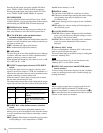
OUTPUT AUTO KNEE Function
BARS OFF Output is a color bar signal.
CAM OFF Output is the camera’s video
signal. The auto knee circuit is
disabled.
CAM ON Output is the camera’s video
signal. The auto knee circuit is
enabled.
Note
Note