


20
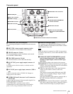
Locations and Functions of Parts
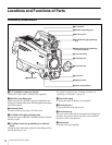
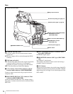
connected, the signal of input 1 is output from this
connector.
j TEST OUT connector (BNC type)
To output the analog signal.
This also supplies the VBS signal, an HD signal nearly
equal to the signal output from the VF connector, an HD-
SYNC signal, or an SD-SYNC signal depending on which
of these you have selected on the menu.
For details on the output signals, see “Setting the Camera
Outputs” (page 31).
k SDI 2 (serial digital interface 2) connector (BNC
type) (HDC1500R)
For HD-SDI or SD-SDI signal output.
For details on the output signals, see “Setting the Camera
Outputs” (page 31).
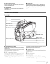
qa SDI (serial digital interface) connector (BNC type)
(HDC1550R/1400R/1450R)
For HD-SDI or SD-SDI signal output.
For details on the output signals, see “Setting the Camera
Outputs” (page 31).
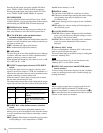
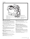
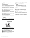
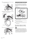
l AUDIO IN CH1 and CH2 connectors (XLR 3-pin)
and switches
Connect audio signals. An input select switch and
microphone power switch are provided for each channel.
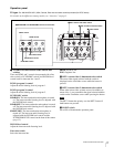
CH1 audio input select switch
Set to the appropriate position according to the equipment
connected to the AUDIO IN CH1 connector.
LINE: When a line-level (0 dBu) signal source is
connected
FRONT MIC: When using the microphone connected to
the MIC 1 IN connector
MIC: When an external microphone is connected
CH2 audio input select switch
Set to the appropriate position according to the equipment
connected to the AUDIO IN CH2 connector.
LINE: When a line-level (0 dBu) signal source is
connected
AES/EBU (HDC1500R/1400R only): When a digital
audio signal is connected (The signal must be in
synchronization with the camera output). The
corresponding position on the HDC1550R/1450R is
invalid (NC).
MIC: When an external microphone is connected
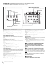
Microphone power switches
When a microphone is connected to the corresponding
AUDIO IN connector, set whether or not to supply a power
to the microphone.
+48V: To supply a power of +48 V
OFF: Not to supply a power
(No function has been assigned to the lowermost position.
No power is supplied to the microphone.)
To supply a power of +12 V, modification of the camera is
required.
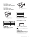
CH 1
48V
OFF
MIC
LINE
48V
OFF
MIC
LINE
AES/EBU
FRONT MIC
AUDIO IN
CH 2
CH2 audio input select switch
CH1 audio input select switch
Microphone power switches
AUDIO IN CH1 connector AUDIO IN CH2 connector
The figure shows HDC1500R.
Note