


16
Locations and Functions of Parts
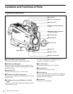
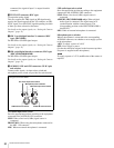
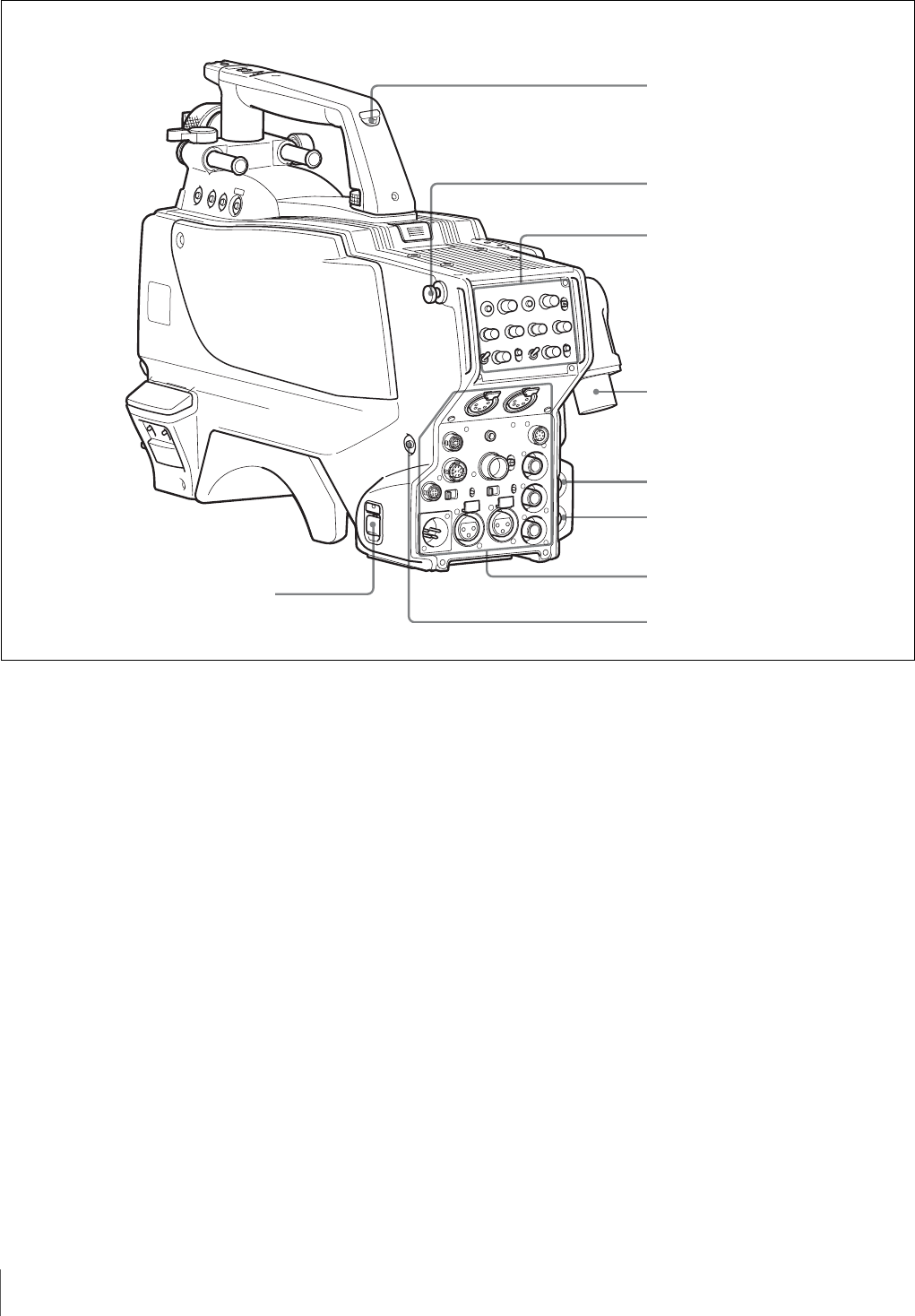
Rear
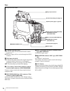
a CAMERA POWER switch
CCU: Power supply will be received from the camera
control unit.
EXT: Power supply will be received through the DC IN
connector.
b Tally lamp and switch
ON: The tally lamp lights when a tally signal is input to the
connected camera control unit or a call signal is
generated in response to pressing of a CALL button.
OFF: The tally lamp is prevented from lighting.
c CCU (Camera Control Unit) connector (optical/
electrical multi-connector) (HDC1500R/1400R)
Connect a camera control unit using an optical electro-
composite cable.
3 HDCU/HDFX (HD Triax CCU) connector (Triax
connector) (HDC1550R/1450R)
Connect the HDFX100 HD Triax CCU Adaptor using a
Triax cable. A camera control unit can be connected via the
HDFX100.
d SDI 1 (serial digital interface 1) connector (BNC
type) (HDC1500R only)
For HD-SDI signal output
e PROMPTER2 connector (BNC type) (HDC1500R
only)
For prompter 2 signal output.
This operates only when a camera control unit having a
prompter 2 input is connected.
f CALL button
When you press this button, the red tally lamp of the RCP-
700/900-series Remote Control Panel or the MSU-900/950
Master Setup Unit, will light. Use to call the operator of the
RCP or MSU.
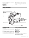
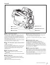
a CAMERA POWER switch
Shoulder strap fitting post (page 12)
c CCU connector (HDC1500R/1400R)
HDCU/HDFX connector
(HDC1550R/1450R)
d SDI 1 connector (HDC1500R only)
f CALL button
Operation panel (page 17, page 18)
Connector panel (page 19)
b Tally lamp and switch
e PROMPTER2 connector
(HDC1500R only)
The figure shows HDC1500R.