


7
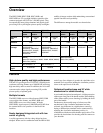
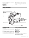
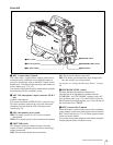
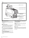
Overview
Detail boost-frequency control
The boost frequency can be adjusted from 20 to 30 MHz.
This allows the detail thickness to be set appropriately for
the subject, thus enabling more subtle image expression.
H/V ratio control
The ratio between horizontal and vertical detail can be
adjusted.
White/black limiter
The white and black details can be limited independently.
Easy menu-based setting
Selections and settings for viewfinder display items,
safety-zone marker
2)
or center marker,
3)
screen size
marker, etc. can be made quickly and easily, using setup
menus displayed on the viewfinder screen or an external
monitor.
2) Safety zone marker:
A box-shaped marker displayed on the viewfinder screen which indicates
80%, 90%, 92.5%, or 95% of the total screen area
3) Center marker:
A cross-shaped marker which indicates the center of the viewfinder screen
Wide variety of viewfinder display options
Along with items such as operation messages, a zebra
pattern,
4)
a safety-zone marker, and a center marker,
camera settings may also be displayed on the viewfinder
screen. Furthermore, there are other indicators arranged
above and below the viewfinder, such as a tally lamp,
battery warning indicator, and an indicator to tell you that
one or more settings are other than standard. This makes it
simple to check the status of the camera.
4) Zebra pattern:
A stripe pattern displayed on the viewfinder screen which indicates the
portions where the video level is above about 70% or 100%. Used to check
the video level of the subject.
Optical digital transmission (HDC1500R/
1400R)
The camera uses electro-optical coding cable for 1.5-
gigabit digital optical transmission between the camera
and a Camera Control Unit.
High-resolution monochrome and color
multiformat viewfinders (optional)
The HDVF-20A/200 multiformat 2-type monochrome
CRT viewfinders and the HDVF-C35W (3.5-type) /
HDVF-C30WR (2.7-type) multiformat color LCD
viewfinders are available as options to cover various
applications.
Prevention of electrical shock
When the power connection is unsafe, the power supply
from the connected Camera Control Unit will be shut off.
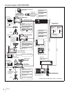
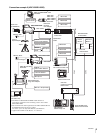
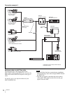
System Configuration
Peripherals and related devices for the cameras are shown
in the figures on the subsequent pages.
Production of some of the peripherals and related devices
shown in the figures has been discontinued. For advice on
choosing devices, please contact your Sony dealer or a
Sony sales representative.
Note