


31
Setting the Camera Outputs
• The level indicator and the effect area marker cannot be
displayed simultaneously, whichever you set to ON later
is preferentially displayed.
• The area marker and the aspect safety marker cannot be
displayed simultaneously, whichever you set to ON later
is preferentially displayed.
• When displaying the focus assist indicators, check that
the flange focal length has been precisely adjusted.
See “Adjusting the Flange Focal Length” on page 21 for
the flange focal length.
Setting the Camera
Outputs
You can specify video signals directly output from the
camera, with menu operations.
The MAIN (camera picture), RET (return video), or VF
(the same picture as that displayed on the viewfinder
screen) setting is common to SD-SDI and VBS. Different
signals cannot be output.
The menu pages used for the output settings have been
registered to the USER menu at the factory.
• <POWER SAVE>
• <OUTPUT FORMAT>
• <TEST OUT>
• <SDI-2 OUT>(HDC1500R)/<SDI OUT>(HDC1550R/
1400R/1450R)
•<DOWN CONVERTER>
Set the following menu items to the settings shown in the
table.
For details on menu operations and the USER menu, see
“Menu Operations” on page 34.
Outputting the signal being shot (camera
picture)
The same textual information as that displayed on the
viewfinder screen can be added to the output signal by
setting CHARACTER to “ON” on the <SDI-2 OUT>
(<SDI OUT>) or <TEST OUT> page.
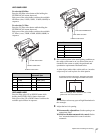
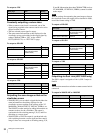
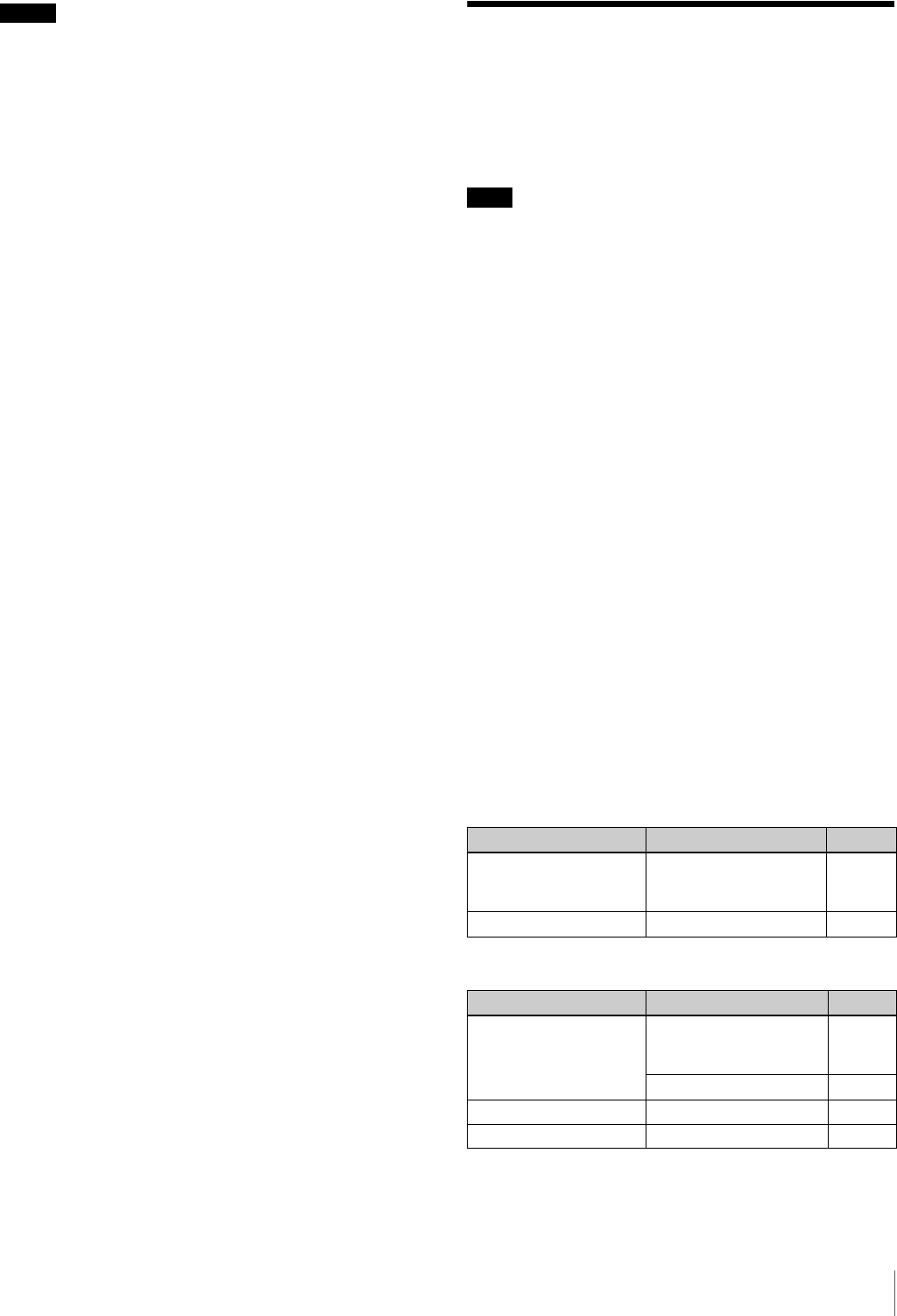
To output as HD-SDI
To output as SD-SDI
Notes
Note
Menu page Item Setting
<POWER SAVE> SDI-2 OUT (HDC1500R)/
SDI OUT(HDC1550R/
1400R/1450R)
ACTIVE
<SDI-2 OUT>/<SDI OUT> OUTPUT MAIN
Menu page Item Setting
<POWER SAVE> SDI-2 OUT (HDC1500R)/
SDI OUT(HDC1550R/
1400R/1450R)
ACTIVE
DOWN CONVERTER ACTIVE
<DOWN CONVERTER> OUTPUT SIGNAL MAIN
<SDI-2 OUT>/<SDI OUT> OUTPUT SD-SDI