


Specifications
Appendixes
A-2(E) Appendixes
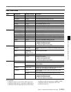
Input/output connectors
CCU Electro-multi connector (1)
LENS 12-pin (1)
VF 20-pin (1)
MIC IN XLR 3-pin, female (1)
AUDIO IN 1, 2 XLR 3-pin, female (1)
EARPHONE OUT Minijack (1), 8 ohms
DC IN XLR 4-pin (1), 10.5 to 17 V
DC
DC OUT 4-pin (1), 10.5 to 17 V DC,
5W maximum
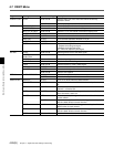
HD SERIAL RET OUT
BNC type (1)
HD SERIAL LINK A/LINK B (Dual Link) OUT
BNC type (1 each)
INCOM1 and 2 XLR 5-pin, female (1)
TEST OUT BNC type (1)
GENLOCK IN/RET IN/PROMPT OUT
BNC type (1), 1 Vp-p,
75 ohms
RET CONT 6-pin (1)
REMOTE 8-pin (1)
TRACKER 20-pin (1)
EXT I/O 20-pin (1)
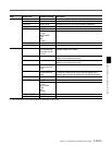
Supplied accessories
Operation manual (1)
Installation & maintenance manual (1)
Viewfinder connecting cable (for HDVF-C750W) (1)
Optional accessories
BKP-L551 Battery Adaptor
BKW-401 Viewfinder Rotation Bracket
C-74 Microphone
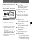
CAC-6 Return Video Selector
CAC-12 Microphone holder
CRS-3P Cradle Suspension
HDVF-20A HD Electronic Viewfinder
HDVF-C30W HD Electronic Viewfinder
HDVF-C750W HD Electronic Viewfinder
HKC-T950 HD CCD Block Adaptor
MSA-4A/8A/16A Memory Stick
VCT-14 Tripod adaptor
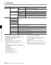
Connectors for optical/electric composite cables:
• LEMO(R) PUW.3K.93C.TLCC96
(to the “CAMERA” connector on CCU)
• LEMO(R) FUW.3K.93C.TLMC96
(to the “CCU” connector on CAMERA)
Caution on the optical/electric composite cable:
For connection between the camera control unit and a
camera, be sure to use an optical/electric signal
composite cable with the connectors specified in this
manual in order to comply with the limits for EMC
regulations.
Design and specifications are subject to change
without notice.